Numerical Indicators
This information did not seem to fit anywhere else, so this page is devoted to it alone
A Survey of Numerical Displays
The display of numbers is frequently required of electronic apparatus. Numeric displays are closely related to alphanumeric displays, which can show letters as well as numbers. Since there are only ten digits, 0-9, numeric displays are simpler, so our discussion will generally be in terms of them. There is a huge variety of displays, both past and present. I'll restrict myself to those that I can actually obtain and test, while perhaps mentioning others that may be of special curiosity. There were the so-called ABC telegraphs in early days that could indicate a great number of characters, and hotel annunciators and other apparatus besides, so the field is not a new one.
The liquid crystal display (LCD) is the favored method at present, because of the very small power required. These displays use ambient light, reflecting or absorbing it as required in a dot matrix or segment display, making use of the capacity of liquid crystals to rotate the plane of polarization of light, while the crystal order is altered by the applied electric field. An alternating voltage of zero average value is used. A computer-controlled dot-matrix display can display numbers, letters and symbols quite flexibly.
Before the LCD came the 7-segment LED display, very visible but thirsty for power. As the name implies, a single digit consists of 7 bars in an arrangement like a figure 8 that can be individually lighted by passing current through the corresponding diode. There may be one or two decimal points that can be lighted. Either the anode or the cathode is common to all segments. In addition to the digits 0-9, other patterns can be lighted for special purposes (including the hex digits A-F), but it is not a general alphanumeric display.
Discrete diodes can also be arranged in a matrix to make an alphanumeric display, each diode representing a pixel. A 5 x 7 display is satisfactory, and can be obtained in a single package. The same thing can be done with incandescent lamps, which were once widely used in advertising displays. There was a Phillips 66 sign somewhere around Grand and Broadway in Oklahoma City that was constantly in motion, ending with the 66 displayed with moving bands. The scoreboard at Mile High Stadium in Denver, demolished in 2000, used computer-controlled incandescent lamps to display photographs and other graphics.
Before the LCD, in the period 1950-1970, the Nixie tube, developed by Burroughs, was a popular display. This was a neon glow tube with screen-like anodes sandwiching ten cathodes, each shaped like a digit. Similar cold-cathode tubes had long been used for decorative displays, usually showing only one pattern, but the Nixie had a serious purpose. These tubes have received considerable current interest through the hobby project of making digital clocks using them. Visit Nixclock for everything about these clocks and Nixies. A Nixie requires about 180 V on the anode, and a typical cathode current is 2 mA. It is a very attractive display.
Before the Nixie was the Dekatron, another cold-cathode neon glow tube, with 30 cathodes in a ring, seen end-on. By manipulating the voltages supplied to the cathodes, the discharge could be made to jump in groups of three cathodes. The lighted cathodes displayed the number, and the tube itself served as a counter, not simply a display only. These were often seen on things like Geiger counters.
There were also neon 7-segment displays, as well as the RCA Numitron, a 7 -segment incandescent filament display. The variety of displays was amazing.
The vacuum fluorescent display (VFD) gives a bright display when an LCD would be too dim. It has a thermionic cathode and an anode of luminescent material in a suitable pattern. The flow of electrons is controlled by a grid between the cathode and anode, just as in a triode vacuum tube, but in an off-on fashion.
An ingenious person has devised a numeric display that is written on a CRT face by what appears to be a vector method. The usual way is to use a raster (scan), and, of course, this is very well known and widely used in television and video monitors.
Experiments
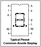 The LED 7-segment display is the easiest to work with, and is a good introduction to 7-segment displays in general. The pinout of a typical display is shown at the right. The segments are usually labelled a-g as shown. The pins are the same as for a 14-pin DIP, and it can be oriented by the missing pins. This represents a common-anode display, in which the anodes of all eight internal LED's are connected together and brought out at the pins labelled "A." One or both A pins can be used. The light from each LED is spread optically to illuminate its segment. There is usually only one decimal point, to the right or the left of the digit. The pin for the missing decimal point is not connected.
To test the display, connect an anode pin to +5 V, and then connect the pin corresponding to any segment to ground through a 470Ω resistor, which will give a current of about 7 mA. This should give satisfactory illumination. The smallest current that is satisfactory should be used, since the displays use a lot of current. Don't forget that something has to limit the current through the diode! In a display connected to a computer, the 7-segment displays are usually scanned for economy. Corresponding segments are all connected together and activated simultaneously, but 5 V is only applied to one anode, so that only that display lights. The displays are activated one by one in sequence, each one displaying its segments for a short time. If 7 mA gives sufficient illumination, and there are 4 displays, then the cathode resistors are chosen to give a current of 4 x 7 = 28 mA. Up to 60 mA is permissible, if it is applied intermittently. To the eye, all the displays will appear to be illuminated.
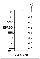 7-segment displays are often used with BCD (binary-coded decimal) decoder chips that take a 4-bit input and have 7 outputs, one for each segment. If 0110 is input, for example, the segments to display a "6" are illuminated. The pinout of a popular BCD-to-7-segment decoder, the 74LS47A, is shown at the left. The BCD input is DCBA, and the corresponding output goes low. To use this chip, simply connect each output with the corresponding segment of the display through a 470Ω resistor, with +5 V on the common anode. The decimal point is lighted by separate circuitry, which can simply be a resistor connected to ground to light it, or leaving the pin unconnected to hide it. The chip will work as you want it to with the three control inputs left unconnected. If you ground "test" all 7 segments will light. If you ground BI, all the outputs will be high, and the display will be blank. If you ground RBI, a zero will be blanked (this is for blanking leading zeros). RBI and RBO are used for a series of digits. We will not use these functions here, but they are there if you need them.
The decoder chip steals some flexibility from you. In particular, inputs greater than hex 9 give funny outputs. They could as well have displayed A - F, as hex digits, but they do not. You can find out what happens by experiment, or in the data sheet for the chip. If you control each segment separately and explicitly, you can display anything, and I think it is best to do this if you have computer control. Without a computer, the decoder chip makes things a little easier, however. Remember that it is not necessary to use a BCD to 7-segment decoder with the display.
The liquid crystal 7-segment display (LCD) is only a little more complicated to use. It has the same 7 segments as an LED display, but now they are determined by transparent electrodes at the front of the display, working against a backplane that is common to all the segments, like the anode in a common-anode LED display. When an electric field is applied, the alignment in the liquid crystal rotates the direction of polarization so that incident light is not reflected, and a dark patch results. There are different kinds of liquid crystals, and different methods of construction, but this is the basic idea. To avoid damaging the liquid, the field must be reversed periodically so that there is no DC component.
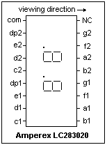 The display I used is an Amperex LC283020 display with two digits and two decimal points. The pinout is shown at the left. The pin marked "com" is the common backplane for all segments. The rest of the pins are for the 14 segments and 2 decimal points. Whatever LCD you have available will have a similar pinout. It operates from 3 to 6 V, with 4.5 V typical, and stands only 100 mV of DC field. The field can reverse in the frequency range of 30-200 Hz. I use 100 Hz, but the exact frequency is not important. This display has a total area of 117.2 mm2, and requires only 30 nA per mm2, so it draws only 3.5 μA! This low current drain is one reason LCD displays are popular, especially with battery-powered equipment. The drawbacks are the lack of self-illumination, and the effects of cold, which slow down the display greatly. The service life of the display is given in the data sheets as 105 hr, which corresponds to 11.4 years of continuous service. LED's have an indefinite service life.
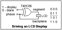 The method of driving an LCD display is shown at the right. HC logic is used because its output goes rail-to-rail and it uses little current. The input "phase" is a square wave with frequency from 30 to 200 Hz. The duty cycle should be very close to 50% to avoid a DC component in the drive. The XOR gate can be controlled so that its output is equal to "phase," giving no field across the LED so the segment will be blank, or so that its output is the complement of "phase," and an alternating field will be impressed across the LCD.
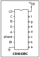 As with LED displays, decoder chips are available for LCD's. A popular one is the CD4543BC, whose pinout is shown at the left. As with the 74LS47, a-g are the outputs, and DCBA the BCD inputs. When BI is high, the display will be blanked. When LD is high, changes in DCBA will be reflected immediately in the digit displayed, but pulling LD low will latch the current value. If a square wave is applied to the "phase" input, the output levels will complement as with the HC86, so the LCD can be driven directly. For a common-anode LED display, simply tie "phase" high. Since this CMOS chip can only drive 1 LSTTL input, a buffer, such as a Darlington transistor, is necessary in this case. A 74HC86 can be used to drive the decimal points. For the Amperex LC283020, two 4543's are needed. The connection is straightforward, so I won't give a circuit diagram. LCD's are too slow to be scanned like LED's. Instead, the output for each one can be latched in the 4543's to make interfacing easy.
Another method of display is the dot matrix, where each dot, or pixel, can be separately illuminated. However, even a small 5 x 7 matrix will have 35 pixels, considerably more than the 7 segments of the displays we have been talking about up to now. For economy, a 5 x 7 display can be controlled as 5 columns of 7 pixels each, and the columns scanned as with multiple LED displays. This requires on 5 + 7 = 12 outputs instead of 35, which is practical. However, computer control is required (or at least is the easiest thing to implement) in this case. Dot matrices give us the greatest flexibility in creating characters.
A very useful form of display has many LCD pixels, each controlled by memory in the display controller, which handles all the work of scanning. All one has to do is write character codes, for example BCD, into the memory, and they will be displayed. Such a display may be, for example, two lines of 32 characters each. These displays also must be managed by a computer, which can talk to the computer on the display. We will not study these displays here, but stick to static displays that we can breadboard.
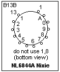 The Nixie (® Burroughs Corp.) indicator tube is a multicathode neon glow discharge that can display the digits 0-9. The Nixie tube that will be used here is the NL6844A, a standard-size, end view tube with digits 0.610" high. The tube itself is 1.080" diameter by 1.125" high, with a 13-pin base. The pinout is shown at the right. The pins are 1.02 mm diameter. Use female sockets from connectors to make connections; don't solder to the pins. The Digi-Key A1029 is a suitable socket. The minimum supply voltage is 170V, the maintaining voltage 135 V, and cathode current is 1.5 mA minimum, 2.25 mA typical and 3.0 mA max. These are simply neon glow tubes, and no harder to use than you would expect. They make a very pleasing pure orange display, with crisp and graceful digits. The anode grille of fine crossed wires forming squares is at the front, with the digits stacked behind it.
Since only one cathode is lighted at a time, a single resistor is connected in the anode lead to control the current. The value of this resistor is given by (V - 135)/I, where V is the supply voltage, and I is the desired cathode current, about 2 mA. The cathodes are easily driven by transistors, the high voltage MPSA42 being a good choice.
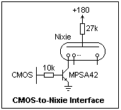 A Nixie can be also driven by a BCD-to-decimal decoder. The 74141 was designed for just this purpose, and is still available from NTE (via Mouser), but at a rather high price ($7.00). Transistors work just as well, with any kind of decoder, at a lower cost. The 4017 decimal counter with decoded outputs is perfect for this purpose. It is easy to set up a 4017 counter with transistor drivers to exercise all the digits of the Nixie. Use an MPSA42 transistor with a 10k base resistor for each cathode, as shown in the diagram at the left. If your power supply is a different voltage, choose the anode resistor to maintain the desired cathode current, 1.7 mA in this case, which gives ample brightness. The maintaining voltage, as stated above, is close to 135 V.
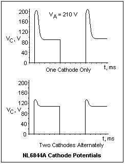 It might be thought that the floating cathode of an unlighted segment would be no problem for, say, an open-collector output of digital logic. This can be investigated with the oscilloscope, and the results are shown at the right. The cathodes were driven by MPSA42 collectors, using 10k in the base lead to the TTL output of the function generator or inverter. We see that immediately after the glow is extinguished, the cathode is connected to the anode by the residual ionization, which does not decay for about a millisecond. Afterwards, the "off" cathode assumes a constant intermediate voltage that is 90 V if no other cathode is lighted, and 113 V if one is. Of course, the disconnected cathode could not supply very much current (here, it is supplying the leakage through the collector of the transistor), but the stresses probably would not do the base-collector junction any good. Therefore, it seems as if the high-voltage transistor is the only completely safe alternative. The 74141 was designed with this problem in mind. A Zener diode is shown in the circuit diagram, but this will not work unless the resulting current is below the maintaining current of the cathode. This probably supplies a pre-bias to permit rapid changes. The 74141 is rated at 60 V maximum.
An alternative to a Nixie for a decimal display is a 10-element bar graph array, which consists of 10 separate LED's in a single compact package. Only one anode resistor, perhaps 330Ω, is required, with a +5 V supply, since only one LED will be lighted at a time. The LED's can be driven by two 74HC05 inverters. It is not nearly as attractive as a Nixie, but is inexpensive and needs no high voltage.
The link in the fifth paragraph above to Mike Harrison's Nixclock site offers a schematic for a Nixie clock (and a gallery of Nixie clock photos). This is not really a clock, but just a counter for the power line frequency, which is usually controlled to give good time on the average. It would be an independent clock if it used a crystal oscillator, which would not be hard to add. However, power line time probably does not drift indefinitely in one direction in the long haul. Harrison's clock uses 4017 counters and MPSA42 transistors. The power supply voltage seems a bit high, but this is apparently no great matter, just a matter of convenience considering the 230 V supply, which naturally gives 340 V when rectified, or a doubler 115 V supply, which gives 250 V (I get a little more with a doubler). It is only necessary to choose the anode resistors accordingly. If you have a variable DC supply, about 180 V would seem ideal. Unfortunately, rectified 120 VAC is borderline, at slightly below 170 V.
When a Nixie is in normal operation, there is an ultraviolet glow in the tube that cannot, of course, be seen. It can be photographed, however, and it must be filtered out for good pictures. If the cathode current is too high, a blue glow can be seen, or other parts attract the discharge. This is deleterious, and the cathode current should be lowered. If the cathode current is too high, the inside of the envelope darkens. For longest life, it is best to keep the cathode current as low as can be tolerated.
It is not very difficult to make a Nixie clock. In fact, it is not hard to make electronic clocks in general. The techniques are discussed in the page on Counters and Clocks. As usual, the greatest problems are mechanical, handling all the wires and things, and making the power supply. In fact, the artistic value of the final product is the most important thing to Nixie clock enthusisasts. I made a superficial search for appropriate oscillators, but found none that were particulary well adapted. It seems the simplest solution would be simply to count down a 1.0000 MHz oscillator in 6 decimal stages (using 4017's) to get 1 Hz, then to count this for the display of minutes and hours. There are crystals (and at least one oscillator) at 32,768 Hz, which yields 1 Hz when divided by 215. These are commonly used with real-time chips for computers. It might be interesting to see if a suitable oscillator could be obtained for a sidereal clock, or for a moon clock, perhaps by "pulling" a crystal oscillator.
Return to Electronics Index
Composed by J. B. Calvert
Created 18 June 2002
Last revised 6 September 2012
 The LED 7-segment display is the easiest to work with, and is a good introduction to 7-segment displays in general. The pinout of a typical display is shown at the right. The segments are usually labelled a-g as shown. The pins are the same as for a 14-pin DIP, and it can be oriented by the missing pins. This represents a common-anode display, in which the anodes of all eight internal LED's are connected together and brought out at the pins labelled "A." One or both A pins can be used. The light from each LED is spread optically to illuminate its segment. There is usually only one decimal point, to the right or the left of the digit. The pin for the missing decimal point is not connected.
 7-segment displays are often used with BCD (binary-coded decimal) decoder chips that take a 4-bit input and have 7 outputs, one for each segment. If 0110 is input, for example, the segments to display a "6" are illuminated. The pinout of a popular BCD-to-7-segment decoder, the 74LS47A, is shown at the left. The BCD input is DCBA, and the corresponding output goes low. To use this chip, simply connect each output with the corresponding segment of the display through a 470Ω resistor, with +5 V on the common anode. The decimal point is lighted by separate circuitry, which can simply be a resistor connected to ground to light it, or leaving the pin unconnected to hide it. The chip will work as you want it to with the three control inputs left unconnected. If you ground "test" all 7 segments will light. If you ground BI, all the outputs will be high, and the display will be blank. If you ground RBI, a zero will be blanked (this is for blanking leading zeros). RBI and RBO are used for a series of digits. We will not use these functions here, but they are there if you need them.
 The display I used is an Amperex LC283020 display with two digits and two decimal points. The pinout is shown at the left. The pin marked "com" is the common backplane for all segments. The rest of the pins are for the 14 segments and 2 decimal points. Whatever LCD you have available will have a similar pinout. It operates from 3 to 6 V, with 4.5 V typical, and stands only 100 mV of DC field. The field can reverse in the frequency range of 30-200 Hz. I use 100 Hz, but the exact frequency is not important. This display has a total area of 117.2 mm2, and requires only 30 nA per mm2, so it draws only 3.5 μA! This low current drain is one reason LCD displays are popular, especially with battery-powered equipment. The drawbacks are the lack of self-illumination, and the effects of cold, which slow down the display greatly. The service life of the display is given in the data sheets as 105 hr, which corresponds to 11.4 years of continuous service. LED's have an indefinite service life.
 The method of driving an LCD display is shown at the right. HC logic is used because its output goes rail-to-rail and it uses little current. The input "phase" is a square wave with frequency from 30 to 200 Hz. The duty cycle should be very close to 50% to avoid a DC component in the drive. The XOR gate can be controlled so that its output is equal to "phase," giving no field across the LED so the segment will be blank, or so that its output is the complement of "phase," and an alternating field will be impressed across the LCD.
 As with LED displays, decoder chips are available for LCD's. A popular one is the CD4543BC, whose pinout is shown at the left. As with the 74LS47, a-g are the outputs, and DCBA the BCD inputs. When BI is high, the display will be blanked. When LD is high, changes in DCBA will be reflected immediately in the digit displayed, but pulling LD low will latch the current value. If a square wave is applied to the "phase" input, the output levels will complement as with the HC86, so the LCD can be driven directly. For a common-anode LED display, simply tie "phase" high. Since this CMOS chip can only drive 1 LSTTL input, a buffer, such as a Darlington transistor, is necessary in this case. A 74HC86 can be used to drive the decimal points. For the Amperex LC283020, two 4543's are needed. The connection is straightforward, so I won't give a circuit diagram. LCD's are too slow to be scanned like LED's. Instead, the output for each one can be latched in the 4543's to make interfacing easy.
 The Nixie (® Burroughs Corp.) indicator tube is a multicathode neon glow discharge that can display the digits 0-9. The Nixie tube that will be used here is the NL6844A, a standard-size, end view tube with digits 0.610" high. The tube itself is 1.080" diameter by 1.125" high, with a 13-pin base. The pinout is shown at the right. The pins are 1.02 mm diameter. Use female sockets from connectors to make connections; don't solder to the pins. The Digi-Key A1029 is a suitable socket. The minimum supply voltage is 170V, the maintaining voltage 135 V, and cathode current is 1.5 mA minimum, 2.25 mA typical and 3.0 mA max. These are simply neon glow tubes, and no harder to use than you would expect. They make a very pleasing pure orange display, with crisp and graceful digits. The anode grille of fine crossed wires forming squares is at the front, with the digits stacked behind it.
 A Nixie can be also driven by a BCD-to-decimal decoder. The 74141 was designed for just this purpose, and is still available from NTE (via Mouser), but at a rather high price ($7.00). Transistors work just as well, with any kind of decoder, at a lower cost. The 4017 decimal counter with decoded outputs is perfect for this purpose. It is easy to set up a 4017 counter with transistor drivers to exercise all the digits of the Nixie. Use an MPSA42 transistor with a 10k base resistor for each cathode, as shown in the diagram at the left. If your power supply is a different voltage, choose the anode resistor to maintain the desired cathode current, 1.7 mA in this case, which gives ample brightness. The maintaining voltage, as stated above, is close to 135 V.
 It might be thought that the floating cathode of an unlighted segment would be no problem for, say, an open-collector output of digital logic. This can be investigated with the oscilloscope, and the results are shown at the right. The cathodes were driven by MPSA42 collectors, using 10k in the base lead to the TTL output of the function generator or inverter. We see that immediately after the glow is extinguished, the cathode is connected to the anode by the residual ionization, which does not decay for about a millisecond. Afterwards, the "off" cathode assumes a constant intermediate voltage that is 90 V if no other cathode is lighted, and 113 V if one is. Of course, the disconnected cathode could not supply very much current (here, it is supplying the leakage through the collector of the transistor), but the stresses probably would not do the base-collector junction any good. Therefore, it seems as if the high-voltage transistor is the only completely safe alternative. The 74141 was designed with this problem in mind. A Zener diode is shown in the circuit diagram, but this will not work unless the resulting current is below the maintaining current of the cathode. This probably supplies a pre-bias to permit rapid changes. The 74141 is rated at 60 V maximum.