Sine Wave Oscillators
The Wien bridge oscillator, Pierce crystal oscillator, Hartley, Colpitts and tuned-gate oscillators
We have already treated several kinds of relaxation oscillators in these units. The sine waves that your function generator creates are made from square waves, by wave-shaping circuits and filters, and are really not very good sine waves, though they do have most of their energy close to one frequency. If you need better sine waves, a linear oscillator will make them. A linear oscillator is very different from a relaxation oscillator. The name "linear" really does not fit, since all oscillators are nonlinear, but a linear oscillator at least does not produce corners and jumps, but a smooth wave. There are many interesting aspects to these oscillators. The most important is probably what determines the amplitude of oscillation and keeps the feedback accurately at -1, so the output has a steady amplitude. An oscillator must also start, and this can be interesting, especially when the oscillator is just able to oscillate, or at threshold. We will not do theory here, but will look at a few practical oscillators, and see how they work.
The Wien Bridge Oscillator
The first is the remarkable Wien Bridge oscillator (named after Professor Wien, and not spelled Wein). This oscillator gives a really beautiful sine wave, and is an excellent choice for a precision audio oscillator. Its characteristic feature is the RC network consisting of R and C in series with a parallel combination of R and C, as shown in the circuit diagram below. The resistors and capacitors can be different in value, but it is much simpler to take them equal, and nothing of value is lost. This network, considered as a passive filter, gives zero phase shift for some intermediate frequency, given by f = 1/2πRC. It is a second-order filter (two capacitors), and this is a remarkable occurence. Work out the transfer function of the network, which is Vo/Vi = jωCR / [1 - (ωCR)2 + 3jωCR]. At the frequency of zero phase, the gain is exactly 1/3.
Use a function generator to supply the network with a sine wave, and use the scope to look at Vin and Vout. It is instructive to use the XY plot and look at the Lissajous' figure. At the frequency of zero phase, the figure will reduce to a straight line, showing this fact. At low frequency, the output leads, while at high frequency the output lags. This kind of second-order filter is called an allpass filter, used for its phase properties rather than for its amplitude properties.
 The circuit for the oscillator is given at the right. The Wien network is seen at the right, arranged to give positive feedback, which an oscillator must have. The op-amp works with a bipolar supply, so the output can swing above and below ground. Note that the Wien network is returned to GND, not the negative supply. On the left is the negative feedback network. When the oscillator is running stably, this must exactly counterbalance the positive feedback. It is impossible to do this with fixed resistors. If the postive feedback dominates, then the op-amp saturates and we have a relaxation oscillator. If the negative feedback dominates, then the oscillator never starts. We must start with positive feedback, and then reduce it as the amplitude increases, and finally maintain constant amplitude by minute adjustment.
 This is usually done with tungsten-filament lamps, as here. If you wish to build the oscillator, you will have to rummage about for suitable lamps. I just happened to have the JKL7876 lamps around, and they were pressed into service. It actually took two in series, but the job can be done with one lamp, if it is suitable. The resistance versus current characteristic for these lamps is shown at the left. Note how rapidly the resistance increases with current. This is just what we need, since a larger amplitude of the output will heat the lamp more, raise its resistance, and decrease the positive feedback. The lamp is heated by the rms value of the alternating current through it, and its thermal inertia means it cannot follow the instantaneous variations. It is affected only by the rms value of the output. Try to find a lamp with about 100Ω resistance when cold (like the two 7876's in series). When the oscillator is running, you should not see the lamp even glowing (though some might). The lamp will last forever in this circuit.
Once you have a suitable lamp, you can make the oscillator and observe its output. When first turned on, the op-amp might saturate, but when the lamp heats up the waveform will spring away and assume a beautiful shape. The amplitude is determined by the interaction of the lamp and R1. To get an oscillator of around 1 kHz, I used R = 15k, C = 0.01. The rms current, determined from the output amplitude of 13.4 V peak to peak, was 9.6 mA, within the capabilities of the op-amp's output. How would you change R1 to get a smaller amplitude? In this case, the resistance of the two lamps in series was 165Ω when the oscillator was running.
Crystal Oscillators
Some crystals develop surface charges when they are squeezed, bent or twisted, and are called piezoelectric. Conversely, when an electric field is appied to them, they expand, contract, bend or twist. The mechanical vibrations of the crystal are directly associated with electrical changes at the same frequency. Like all mechanical systems, crystals may vibrate at resonant frequencies, where small pushes create a large amplitude, just as in electrical resonant circuits. The mechanical vibration of crystals gives a standard of time, better than that of mechanical clocks, but inferior to that of atomic vibrations.
 Quartz is a piezoelectric material, not the most sensitive, but so very stable mechanically and electrically that it is almost the only resonant crystal used. A thin plate will vibrate at megahertz frequencies, so the crystals are used in radio-frequency circuits. The vibrations most often used are not the simple thickness vibrations of an elastic plate, but are more complicated shearing modes that provide the desired frequencies and the best independence of temperature. The equivalent circuit of a crystal, shown in the figure on the left, consists of a capacitance C1 (of the metal electrodes on two opposite surfaces) in parallel with a series RLC circuit representing the crystal itself, called the motional arm, in which the equivalent value of L is surprisingly large. It is this that makes the crystal such a good frequency standard.
 The reactance of a crystal varies with frequency as shown at the right. At both low and high frequencies, it appears capacitive, with a short interval between the series and resonant frequencies where it looks like an inductance. A typical crystal might have C = 10 fF (.010 pF), L = 2 H and R = 50Ω, which gives a series resonant frequency of fs = 1/2π√(LC) = 1.125 MHz. The Q of the resonance is Q = ωL/R = 141,400, so the width of the resonance is only 8 Hz. The parallel resonant frequency fp is a little higher, the exact amount depending on C1 and the external load capacitance. By varying the load capacitance, the resonance frequency can be adjusted slightly, which is called pulling the crystal. Depending on the circuit, the crystal can resonate in either the series or parallel mode, and in either case will control the frequency.
 The simplest crystal oscillator is the Pierce oscillator, shown in the figure on the left. An FET is used as the amplifying device, since it provides a high input resistance that allows the use of a 10M gate resistor. The crystal had a frequency of 2.000 MHz, but any reasonable crystal can be used. The 3.3 mH RF choke gives a high load impedance to alternating current, while passing the DC drain current without voltage drop (the choke had a resistance of 41Ω). The choke must be specially designed to retain the desired inductance while it carries DC, so make sure the choke you use is designed for the purpose. The impedance of the choke is over 41k at 2 MHz, which gives sufficient gain.
The crystal is the only resonant element in the circuit, and so must determine the frequency of oscillation. It is connected as for shunt-shunt feedback. Here is a case when instability is desired, and there is a 180° phase shift at resonance, making the feedback positive. The amplitude is limited by the maximum range of the voltage excursions at the drain. The resistor R can be used to reduce the feedback and the crystal drive. It is not required for oscillation, and if you look at the output wavform when it is zero, you will see a waveform flattened above and below. With R = 10k, the waveform is much more sinusoidal, especially the upper parts, but the lower part is still noticeably flattened. With R = 15k, the oscillator will not oscillate (it does not start). Crystals, incidentally, must not be driven with too high a voltage, or the mechanical stress will break them. The amplitude of oscillation at the drain was 24 V with R = 1k, the RF voltage across the choke reversing in direction during the cycle.
Tuned-Gate Oscillators
 The oscillators studied here are based on the circuit on the left, which shows the principles. Component values are not shown, because this circuit has not been built and tested yet, and is here for illustration only. Q is an FET, with high input resistance and self-limiting drain current, both of which features are important here. A triode vacuum tube could also be used, which has the same characteristics. When the circuit is quiescent, the resistor Rg, called a grid leak (from vacuum-tube days) provides VGS = 0, and so the drain current is IDSS, and the FET is prepared to amplify. The tuned circuit L1C provides an oscillating voltage to the gate through blocking capacitor Cg when excited. The drain current then varies sympathetically, and is coupled through the mutual inductance M12 to the tuned circuit. If the polarities are properly arranged, the oscillations in the tuned circuit are encouraged, and if the losses are counterbalanced, the oscillations continue and even increase. When the gate becomes positive by about 0.7 V, current through Rg pulls the gate negative, decreasing the gain until the losses are just compensated, and the amplitude of oscillation is steady. When this occurs, the gate becomes quite negative, even beyond cutoff, and the drain current decreases. All the oscillators studied below operate in this way. The grid leak solves the basic problems of every oscillator: starting, and amplitude limiting. The diode D is there only to ease the load on the gate when starting; it has no effect when the oscillator is in operation.
This circuit is called an Armstrong oscillator to honor Major Armstrong, who invented the regenerative receiver, and much else besides in radio. He added the tickler coil L2 that provides positive feedback. If L or C is varied, the frequency of oscillation changes, and we have a variable-frequency oscillator, or VFO. LC tuned circuits do not provide good frequency control, but with effort relatively stable VFO's can be built. Oscillators with air-core inductances are quite practical at radio frequencies (above, say 250 kHz). Note that the inductance of an air-core coil is not affected by DC in the coil. The circuit shown is called series-fed because the bias and signal flow in the same drain circuit (the power supply should be bypassed with a capacitor so it is a good signal ground). The drain could also be shunt-fed, as in the Pierce oscillator above, by using an RFC and a capacitor to separate bias and signal.
 Two modes of feedback are shown at the right. In the Hartley circuit, the inductor is tapped to match the low impedance of the collector circuit (or plate, for a tube), while the other end supplies the base (or grid). Only one capacitor is used, which makes tuning easy. The Colpitts circuit does not require a tapped inductor, but uses two capacitors as a capacitive voltage divider. The phase is opposite at the two ends of the tuned circuit, providing the necessary positive feedback. The frequency is f = 1/2π√LC. In usual high-frequency RF circuits, L is in μH and C in pF.
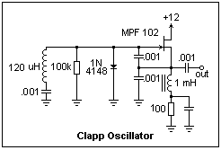 A modification of the Colpitts circuit, called a Clapp oscillator, is shown at the left. This circuit can be built and tested. The tuning capacitor is in series with the inductance; here, it is a fixed capacitor, but in a VFO it would be variable. All three capacitors are 0.001 μF in this circuit, but in a practical circuit, the capacitance in series with the inductor would be much smaller than the other two (perhaps 50 pF), and would give a considerable range of frequencies. The inductor was a 120 μH (shown as uH on schematics) ferrite core inductor I happened to have on hand. The 1 mH inductor in the source lead is a radio-frequency choke or RFC, designed to retain its inductance when a reasonable DC current passes through it. Here, it separates the bias circuit from the RF circuit. The leads of the MPF 102 JFET are DSG, in that order, when looking at the flat side of the package with the leads downward.
This circuit gave a 5 V peak-to-peak signal at the source at a frequency of about 828 kHz, appropriate for a 120 μH inductor resonating with 1/3 nF--the three .001 capacitors in series. The average gate voltage was about -4.5 V, which meant that the gate varied from about -10 V, well beyond cutoff, to +0.7 V, limited by the diode. The average drain current was 0.6 mA. The JFET is operating as a Class C amplifier in this circuit. This makes an excellent RF oscillator for other purposes, if you do not have a signal generator.
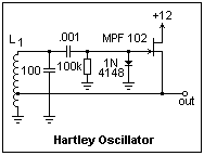 A Hartley oscillator is shown at the right. It uses most of the same components as the Clapp oscillator. A capacitor is necessary to block the gate bias voltage from the tuned circuit. The tuning capacitor is a 100 pF poly capacitor. L1 is a coil wound with #30 wire on a 1/2" form--I used a lucite tube. It has 210 turns, tapped at the 45th turn, and is about 3" long. The tube makes a nice handle while winding the coil, and is cut off when the winding is finished. The ends of the coil can be put through #60 holes in each end. When you get to the 45th turn, scrape off a little of the enamel with sandpaper and solder the tap wire to it. This is a delicate operation, but not really difficult. The turns can be secured with coil dope, if you have it. If not, just use transparent tape or nail lacquer. Solder #22 leads to each of the three wires.
My oscillator went at 1.67 MHz. The inductance of the coil can be estimated from the formula L = D2N2/(18D + 40L) μH, where D is the diameter and L the length of the coil in inches, and N is the number of turns, which gave 85 μH. With 100 pF, this predicts a resonant frequency of 1.73 MHz, close enough agreement. There was a very noticeable parasitic oscillation at about 10 MHz, caused by stray capacitance with the long, looping leads to the coil; better layout would cure this. The gate operated at -5.86 V, and the output was again about 5 V peak to peak. It is very satisfying to see the oscillator work with coils you wound yourself.
Other oscillators are discussed on other pages, for example The VTVM and GDO, where the grid-dip oscillator is studied, and Vacuum Tubes, where local oscillators for superheterodynes are presented.
Return to Electronics Index
Composed by J. B. Calvert
Created 30 July 2001
Last revised 13 May 2002