The Blocking Oscillator
Yet another oscillator, one that is not commonly seen these days, but which is quite interesting
The blocking oscillator is closely related to the two-transistor or two-tube astable circuit, except that it uses only one amplifying device. The other is replaced by a pulse transformer, which provides strong positive feedback at all frequencies. As a monostable, it was useful in the 1950's for producing what were then short pulses, in the microsecond range. It was much faster than the Abraham-Bloch monostable. It the transistor era, however, it fell from grace because it could not be miniaturized, since it requires a transformer, and was also rather hard on transistors. It is an interesting circuit, however, and is worth study. Its theory, which is difficult and not exceptionally enlightening, will not be explained here. We shall be satisfied by observing its actions in the laboratory.
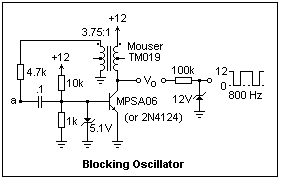 A transistor blocking oscillator is shown at the right. The transformer is phased so that any increase in collector current pulls the base up, further increasing the current. The transformer seemed the most appropriate of those I had on hand, but may not be optimum. The 10k resistor biases the transistor on, so that any fluctuation in the collector current is fed back and reinforced. The base is eventually driven strongly negative, and the transistor is cut off. Periods of conduction and cutoff then succeed automatically. A pulse-shaping circuit is shown at the output. The series resistor and Zener limit the maximum value of the wave to +12V (inductive effects make it considerably larger at the ouput, up to 20V and starting with ringing). Study the circuit with the oscilloscope to understand how the base and collector voltages vary.
Two components are in this circuit to protect the transistor from harm. The more necessary is the Zener diode across the emitter junction. Without it, the base would be driven to -8 V in this circuit, which soon destroys the emitter junction. This is a disadvantage of transistors, one of the few. The emitter must be heavily doped to ensure that the injected carriers of one type predominate, so that a high beta can be achieved. Unfortunately, at the same time this reduces the reverse breakdown voltage of the junction to only about 5 V. The Zener does not improve the action of the circuit--in fact, it makes the duty cycle depart from 50% and has other deleterious effects, but these are not serious.
 The 4.7k resistor is to damp the oscillations when the transistor is turned off at the end of a period of conduction. A particularly atrocious waveform at the collector when the circuit is used as a monostable is shown at the left. There is a nice, sharp leading edge as the transistor turns on. When the transistor turns off, however, there is a strong ringing. Without the 4.7k resistor, and with a 10k resistor between base and ground, the first oscillation was from +30 V to -8 V. A high-voltage transistor (such as the MPSA06) avoids any problem with collector breakdown, but the strong ringing is not desirable. A smaller value of the base resistor also helps; 1k gives only moderate ringing. In the circuit above, the Zener in the ouput clipper also clips off the ringing. The usual cure for turn-off transients, a diode across the offending inductance, does not work here because it destroys the necessary inductive action.
 A blocking monostable is shown at the right. The 10k resistor pullup has been removed, so the normal state of the transistor is "off." A positive pulse at node "a" will start conduction, and the transformer will do the rest. After the brief excursion of conduction, in which the output falls to near ground, the transistor will again be turned off (by a hefty negative pulse to the base). In this circuit, the trigger pulses are provided by an RC differentiating circuit, which produces narrow pulses, alternately positive and negative. The monostable responds only to the positive pulses, which need only be about 1V high. For every positive pulse, the circuit will produce one low-going pulse of brief duration. If the circuit is followed by a phase inverter, the pulses will be a normal string of positive pulses. No effort has been made to make the pulses as short as possible; these will be 100-200 μs wide.
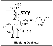 A vacuum-tube blocking oscillator is shown at the left. No extra components are necessary, since the tube can tolerate large negative swings of the grid with no difficulty whatever. This circuit does not "block" strongly; perhaps a different transformer would produce a stronger effect. The oscillation is very stable, the grid swinging from 0 to -15 V, and the plate only 8 V peak-to-peak. The maximum plate current is a most a milliampere or two, so nothing is being pushed to excess in this circuit. There are several possibilities for further investigation. By changing transformers, can the plate excursion be made larger? How does the frequency depend on the component values? [Changing the capacitor from .002 to .001 altered the frequency from 1.34 to 1.65 kHz.] What happens if a low-μ triode (such as a 12B4) is used instead of the high-μ 6SF5?
To make the circuit monostable, the bottom of the 100k resistor should be connected to a C supply and brought negative enough to turn off the tube. For a 6SF5, only a couple of volts will do. Then the circuit can be triggered just as in the case of the transistor monostable. This will work better if you can get the circuit to block more strongly.
 An audio oscillator that can be made quickly and cheaply is shown at the right. The transformer is a small 6.3 V filament transformer (Radio Shack 273-1384), but any audio output transformer could be used if you have one handy. The transformer must be properly "phased." If the circuit does not oscillate when you try it, interchange the secondary connections. Circuits like this were once common in "code-practice" oscillators for amateur radio operators, giving an audio note similar to that of a beat-frequency oscillator in a radio receiver. My circuit oscillated at about 400 Hz, but the exact frequency will depend on the components. The 0.1 μF capacitor has the most influence on the frequency, and can be increased or decreased to vary the frequency. The 0.01 μF capacitor eliminates very large spikes that occur in its absence when the transistor is switched off. If you use a high-voltage transistor, such as the MPSA43, instead of the 2N4124, you can investigate these spikes and the waveform. The output voltage at the collector is about twice the supply voltage in this circuit, and anything from +5 to +12 V gives reasonable loudness.
Return to Electronics Index
Composed by J. B. Calvert
Created 25 November 2001
Last revised 28 April 2002