Varactors
Varactor Theory
A varactor is also known as a variable capacitance diode or a varicap. It provides an electrically controllable capacitance, which can be used in tuned circuits. It is small and inexpensive, which makes its use advantageous in many applications. Its disadvantages compared to a manually controlled variable capacitor are a lower Q, nonlinearity, lower voltage rating and a more limited range. Background material on varactors can be found in the Reference.
Any PN junction has a junction capacitance that is a function of the voltage across the junction, as discussed in any account of PN junctions. The electric field in the depletion layer that is set up by the ionized donors and acceptors is responsible for the voltage difference that balances the applied voltage. A higher reverse bias widens the depletion layer, uncovering more fixed charge and raising the junction potential. The capacitance of the junction is C = Q(V)/V, and the incremental capacitance is c = dQ(V)/dV. The capacitance to be used in the formula for the resonant frequency is the incremental capacitance, where it is assumed that the voltage excursions dV are small compared to V. Finite voltages give rise to nonlinearities. Efforts may be made to reduce these nonlinearities in some cases.
The capacitance decreases as the reverse bias increases, according to the relation C = Co/(1 + V/Vo)n, where Co and Vo are constants. Vo is approximately the forward voltage of the diode. The exponent n depends on how the doping density of the semiconductors depend on distance away from the junction. For a graded junction (linear variation), n = 0.33. For an abrupt junction (constant doping density), n = 0.5. If the density jumps abruptly at the junction, then decreases (called hyperabrupt), n can be made as high as n = 2. I expect that the doping on one side of the junction is heavy, and the depletion layer is predominately on one side, but this is a constructional detail.
Availability of Varactors
For the experiments described below, I used some varactors that were furnished by a surplus house. These were in the TO-92 package that is so convenient for experiments, and came in matched sets of three. A look in the Digi-Key catalog revealed that although a variety of varactors from Zetex are available and inexpensive (p. 398), they are available only in the SOT-23 surface-mount package. This is another example of how things are becoming more difficult for those trying to learn about electronics.
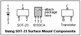
 The solution for this problem is offered by the "Surfboards" of Capital Advanced Technologies (p. 752). These are small boards, as shown at the right, with SIP pins (inline pins at 0.1" spacing) and pads suitable for surface-mount devices. Discrete devices, like our SOT-23 diodes, can be easily soldered to the 6000-series Surfboards. The 6103CA, which holds one device, is suitable. The connections are shown at the right. If you buy your Surfboards from Digi-Key, you will get instructions on how to use them. The methods described here can also be used with surface-mount transistors and components, which will also fit on the Surfboards. This seems to be a practical way to use surface-mount devices when you are compelled to do so.
I used the following tools: a 12W fine-tip soldering iron (Weller WM120);
.025" dia. 60/40 rosin-core solder; fine-point tweezers; a round toothpick; clear household cement; a 10X magnifier for inspection; and, finally, a bright light. Remove the diode by pulling off the clear tape on the carrier. The SOT-23 package is seriously tiny! Make sure you can recognize top and bottom. Lay the 6103CA face-up. Put a small drop of cement on the end of the toothpick, and deposit a tiny amount at the point where the package will be attached. Then place the package on the dot of cement with the tweezers, with its feet in the proper places, and press down. This holds the package while it is being soldered, and is a step that should not be omitted. The tip of the soldering iron should be tinned. Touch the solder to the tip so that a small drop is left hanging on the tip. Now, very carefully bring the drop into contact with the pad of the package and the foil of the 6103CA board at one of the feet of the SOT-23. Capillary attraction will soon cause the solder to spread in the usual way. Press down lightly to ensure that the package is seated. This all takes only a second. Examine the joints with a 10X magnifier to make sure that the feet are entangled in the solder. It's a good idea to put a label on the back of the 6103 to identify the part, since the SOT-23 package is too small for identification.
Experiments
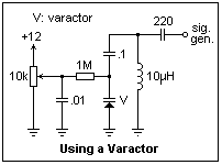
 The basic circuit for testing a varactor is shown at the right. The key is the 1M resistor that isolates the DC voltage source from the circuit attached to the varactor. The 0.1μF capacitor blocks the DC bias voltage. I happened to have a 10μH inductor at hand, one of those that looks like a fat resistor, and has a reasonably high Q. The RF signal generator was coupled through a 220pF capacitor, and set for an unmodulated output. Because of stray capacitances, we cannot accurately measure the capacitance of the varactor with this circuit, but we can certainly see its action.
A capacitance meter did not give satisfactory results, so another method closely related to the actual application of the varactor was used. While observing the voltage across the tuned circuit with an oscilloscope, I varied the frequency looking for a maximum. From the resonant frequency, I then calculated the capacitance using the usual formula.
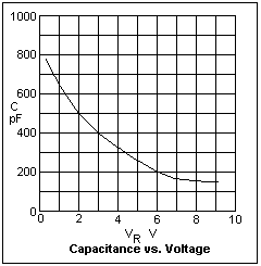
 The results of a series of measurements is shown at the left. The capacitance varied from about 170 pF at 8 V to 750 pF at 0.5V, a satisfactory range. If you plot the frequency vs. the voltage, the result is almost linear, showing that the varactor is of the hyperabrupt type, since n = 2 will give frequency proportional to voltage. I also determined that the MPN3404 that I found in the varactor drawer was probably not a varactor. It was not described, but was listed, in the Motorola data book.
Further experiments will be described, with applications, when I obtain some more varactors.
Reference
S. Hollos and R. Hollos, Circuit Cellar, 139 (Feb. 2002), 50-54.
Return to Electronics Index
Composed by J. B. Calvert
Created 10 February 2002
Last revised 15 February 2002
 The solution for this problem is offered by the "Surfboards" of Capital Advanced Technologies (p. 752). These are small boards, as shown at the right, with SIP pins (inline pins at 0.1" spacing) and pads suitable for surface-mount devices. Discrete devices, like our SOT-23 diodes, can be easily soldered to the 6000-series Surfboards. The 6103CA, which holds one device, is suitable. The connections are shown at the right. If you buy your Surfboards from Digi-Key, you will get instructions on how to use them. The methods described here can also be used with surface-mount transistors and components, which will also fit on the Surfboards. This seems to be a practical way to use surface-mount devices when you are compelled to do so.
 The basic circuit for testing a varactor is shown at the right. The key is the 1M resistor that isolates the DC voltage source from the circuit attached to the varactor. The 0.1μF capacitor blocks the DC bias voltage. I happened to have a 10μH inductor at hand, one of those that looks like a fat resistor, and has a reasonably high Q. The RF signal generator was coupled through a 220pF capacitor, and set for an unmodulated output. Because of stray capacitances, we cannot accurately measure the capacitance of the varactor with this circuit, but we can certainly see its action.
 The results of a series of measurements is shown at the left. The capacitance varied from about 170 pF at 8 V to 750 pF at 0.5V, a satisfactory range. If you plot the frequency vs. the voltage, the result is almost linear, showing that the varactor is of the hyperabrupt type, since n = 2 will give frequency proportional to voltage. I also determined that the MPN3404 that I found in the varactor drawer was probably not a varactor. It was not described, but was listed, in the Motorola data book.