New York Central Signals in 1912 and 1918
This article reviews rule books of 1912 and 1918 to see what they reveal about signaling and train operation during this period of rapid change, especially the more unusual practices. In 1912, the company name was the New York Central and Hudson River Railroad, but by 1918 "and Hudson River" had been dropped. The other companies making up the New York Central System, such as the Lake Shore and Michigan Southern, the Chicago, Cleveland, Cincinnati and St. Louis (Big Four), the Michigan Central and the Boston and Albany, issued their own rule books. The New York Central had been formed in 1869 by the amalgamation of the chain of smaller companies between Albany and Buffalo, as had always been intended. The Vanderbilts added the Hudson River Railroad between New York and Albany, and the New York and Harlem, to create the NYC&HRRR. The main line from Manhattan to Buffalo was 442 miles long, and the New York, New Haven and Hartford entered Manhattan over its rails.
After steam locomotives were banned south of 42nd St., the new Grand Central Station was opened by the New York and Harlem in 1875, with multiple tracks depressed beneath Fourth Avenue (now Park Avenue). The NYC&HR diverged at Mott Haven, and the NYNH&H at Woodlawn. This smoky, busy artery was a source of great operational difficulty, and it was clear that the usual methods of operation relying on flagmen would be unsatisfactory. Daniel Rousseau's automatic signals were installed in 1873 on the first three miles, and by 1876 the signals extended for 16 miles, about to Yonkers. Fatal difficulties soon became apparent, and the signals were abandoned. Other inventors met with similar lack of success.
The NYC&HR steadfastly relied on timetable and train order operation, with trains protected by flagmen. Its answer to the Pennsylvania's block system, introduced in 1874, was to four-track its main lines, beginning with Schenectady to Utica, thereby separating fast and slow trains, making flagging more reliable. "Dutch Clocks" were provided at some stations to show the time since the previous train had passed, as well as manual semaphores to enforce the time interval. 14 miles of Hall enclosed disc signals were installed on a portion of the line beside the Hudson where curvature limited vision. The safety record was very good, showing that the company enforced good discipline. There were accidents, however, which a block system would have prevented, due to bad flagging. At Hastings, New York, a flagman relied on his knowledge that the train following his was a local booked to stop at Hastings, which could easily be stopped without going back. Unfortunately, this train had been delayed and its place was taken by the crack St. Louis Express, which roared into Hastings at speed. It was probably public pressure exerted by newspapers, and negative comparison with other companies that had adopted the block system, that led to a complete reversal of policy around 1892.
The troublesome Park Avenue tunnel was equipped with controlled manual block in 1892. This was a direct import from England, where it was called "lock and block" or the "Sykes" after its inventor, and was supplied by Union Switch and Signal, which had long-standing relationships with English signal manufacturers. At the time, it was being resisted by English railway managements as unnecessary and expensive, so the NYC&HR installation was quite a victory for Sykes. It was eventually installed on the complete main line to Buffalo, and to Boston as well on the NYNH&H. The NYC&HR was the largest user of controlled manual block in the United States, where most other installations were on short critical segments of track.
Under controlled manual block, when a signalman desires to clear his block signal and admit a train to the block in advance, he must first ask the signalman in advance to release his lever. If this signalman agrees that a train can be admitted, he presses a plunger on an instrument in his office, which electrically unlocks the signal lever of the signalman in rear. With the Sykes apparatus, a small semaphore arm drops in the two instruments, and a window changes from LOCKED to FREE. There is a track circuit at each office, between the home signal and the block signal (in England, the starter). When a train occupies this track circuit, the block signal is automatically restored to Stop, and the lever is locked so that it cannot be cleared again. Until the train occupies and then releases the track circuit at the far end of the block, the signalman there cannot plunge and unlock the signal in the rear. This ensures that each clearing of the block signal admits one train and one train only. The use of the home and block signals, and the station limits between them, was unusual in American practice, which normally just used the train order signal as a block signal as well.
 The controlled manual block also brought in English-style bells for communication between signalmen. An extract from the bell code is shown at the right. These were probably single-stroke bells, but a mention in the rule book of one short and one long as requesting that the signalman pick up the telephone is not consistent with single-stroke bells. In American manual block systems, little care was taken to ensure that the track was clear a sufficient distance in advance (beyond) the block signal, while in England a 1/4-mile clearance was strictly enforced. If the clearance space was obstructed, the oncoming train was specially warned that this was the case, and that approach should be with caution. The NYC&HR used a green Advance Card for this purpose. Although the block signal was at Proceed, if there was a train at the station in advance or switches were being used there, then the Advance Card was issued to show that the signals should be approached with extra caution. Normally, a through train expects signals and track to be clear for a through run, and the clearance space allows for the effect of encountering an unexpected stop.
To see how this goes, let's suppose that A is the signalman at a station, and he has previously plunged for the signalman C in his rear. He receives 4 bells and the small semaphore shows that there is a train now in the block. He answers C with 1 bell. Now he gives B, the signalman in advance, 3 bells, asking for unlock, and notices that he is unlocked and the small semaphore has dropped. He clears his signals, and waits for the train to arrive. When it passes, he restores his signal levers to normal (the signals have already gone back to Stop), and if he sees the markers on the train that has just passed, he gives 2 bells to C, who answers with 1. Now he gives 4 bells to B, who answers with a single bell. The times of all these bell signals are recorded in the block record.
 The usual telegraph manual block was also introduced. The regular telegraph offices where train orders were handled were the block stations, the train order signal was also the block signal, and the operator was the block signalman. Communication was by telegraph. Block messages were given by numbers, as shown at the left, beginning with 7. In case the telephone was used, the messages were read out and the numbers were not used. Installing the manual block was very cheap: no additional equipment or personnel was required. Suppose A and B are two successive operators on single track. If, say, No. 44 is approaching A, he sends to B: "74 for 44". B puts his signal to Stop (if not already there) and replies: "75 for 44". Now A can clear his signal (if there are no orders for no. 44) and, when No. 44 arrives, send to B: "77 No 44 Eng 4002 at 9 23 am". Finally, when the train passes B, B sends to A: "75 No 44 Eng 4002 at 9 53 am". The times of the telegraphic signals are noted in the block record. On double track, the operator could display Proceed on the strength of the block record, but would notify the operator in advance when the train entered the block. The manual block system did not modify any of the rules for movement by timetable and train order, and so was an additional safeguard, not the primary one.
 Train-order signals were identified by round-end blades. Normally, they showed only one light, but between 1912 and 1918 were distinguished in automatic block territory by showing two lights in a horizontal row. It is not clear whether two lamps were used, or one with a reflector, as on the Pennsylvania. There could be no objection to using two ordinary lamps, as if one was extinguished, the proper color would still be shown. The figure below shows the usual arm shapes and painting. A square end was used for interlocking signals, a pointed end for automatic block signals, and a round end for train order and manual block signals. Main arms were red, with a white bar, chevron, or curved bar. The backs were white with black bars or chevron. Distant arms were yellow with a black chevron, the backs white with a black chevron. Note that the automatic block signal has a permanent red marker diagonally across the post from the main light.
 A very unusual signal aspect was used to indicate that the block system ended at that point, and trains should proceed further only at what we now call restricted speed. These signals had a fixed distant arm mounted exactly behind the main arm. When the signal was at Stop, the distant arms would not be visible, but would appear when the signal was cleared.
An extraordinary omission in both rule books is the complete absence of any definition of the speeds at which trains were to proceed. The terms "restricted speed", "limited speed", "slow speed", and "with Caution" are used with no hint as to what they mean. In fact, "limited speed" in the 1912 rule book becomes "restricted speed" in the 1918 rule book, and both clearly mean what we would now call "medium speed". In fact, the ARA used "restricted speed" in this sense in 1915, but did not bother to define it."Slow speed" even seems to mean two different things in the same rule book, one what we would call "restricted speed", and the other our current slow speed. However, there are no specifications in miles per hour. Of course, there must have been some understanding of what was intended, but confusion would be more than likely.
A special case is the use of "with Caution". The term "Caution" is still used in Britain, where "Safety" and "Danger" are the other two basic indications. These words were also used in the U.S., but around the time of these rule books objections were raised to them, and they were soon replaced by 'Proceed", "Approach" and "Stop", which clearly communicate the desired actions. If an engineman is instructed to "Proceed with Caution" by a certain signal, does this mean that otherwise he is to "Proceed without Caution"? It is much more satisfactory to define "Proceed with Caution" as, for example: "Proceed prepared to stop within half the range of vision, looking out for trains, obstructions or broken rail, but not exceeding fifteen miles per hour." This became called "restricted speed". The actual ARA Standard Code definition was: "Proceed prepared to stop short of train, obstruction, or anything that may require the speed of a train to be reduced", but this definition was not adopted until 15 May 1924.
There is a plausible reason for the lack of speed definitions in the Standard Code. The ARA scrupulously avoided making any prescriptions that should be a matter for the company involved, especially with regard to speeds and distances. Even after 1924, the speeds prescribed for medium and slow speeds were blanks to be filled in by the company adopting the code. Earlier, it was not made clear that the individual companies should define the speeds appropriately for their conditions, so the New York Central, and probably other companies, simply copied the Standard Code without the necessary complements.
 The diagram at the right shows the shape of switch targets current in 1912 and 1918. The earlier targets show the adoption of green for clear and yellow for caution, replacing white and green, respectively. The 1918 targets use lunar white to show that a switch is lined for the lead, which was a frequent practice. The targets for an open switch are the "spectacle" form familiar from the Pennsylvania. Low swiitch stands show yellow for a closed switch instead of green. In 1912, they could be either color. The 1918 targets show a much greater distinction between those for an open switch and for a closed switch.
 By 1912, the Patenall three-position upper quadrant semaphore was already used for all new installations, but lower-quadrant signals were still common. Turnouts that could be negotiated at 30 mph (No. 15 frogs and long points) were used for main-track crossovers and junctions, and a signal indication to approach them at medium speed (then called either limited or restricted speed) was necessary. The solution was to add a second distant arm to the signal in rear of the signal governing the crossover or junction to indicate that it was to be approached at medium speed, instead of prepared to stop. The aspects used are shown in the diagram at the left. Note that the Proceed aspect is shown with the second distant arm horizontal, green over green over yellow, rather than with all three arms depressed, green over green over green, which might be thought more logical. The lowest arm depressed simply "helps" the usual Approach aspect. This aspect could also be used for four-block signaling as an advance approach. If signals are equally spaced, a train decelerating normally to stop at the second signal will pass the next signal at greater than medium speed, which is the reason the indication "Prepare to stop at the second signal", or Advance Approach, was used by some companies. The New York Central and the Pennsylvania both used Approach Medium in this case, which somewhat extended the necessary braking distance. The three-arm signals had disappeared in the 1918 rule book, replaced by upper-quadrants that could display yellow over green, Approach Medium, with only two arms.
 Hall enclosed disc signal still appeared in the 1912 rulebook, though they had vanished by 1918. The Proceed aspect showed a green light, but the withdrawn disc still showed the white interior of the housing. Distant arms showed a yellow disc and yellow light, or a green light, and again the white housing. Before the change in signal colors, the home arms had displayed red and white, and the distant arms green and white, of course. The signals that remained in 1912 were probably more recent replacement of the originals, worked by track circuit instead of by treadles and wire circuits, as the originals were. The mechanisms were probably the new ones with Z-armatures and holding coils. The later Hall signals had a circular opening in the back of the case, which made the aspect when the disc was withdrawn quite distinctive. The colors of the discs were probably never very important. The NYC&HR probably never used the Union clockwork banner signal that was popular in New England, and was used on the NYO&W in its own territory.
The Patenall 3-aspect upper quadrant signal was adopted as standard by the ARA in 1903, and represented the majority of signal installations between then and about 1940, when light signals became dominant. A three-arm signal, with two upper arms 7 ft. apart and a shorter lower arm at a spacing of 6 ft., could satisfy all requirements at an interlocking. If it was unnecessary, the middle or lower arm could be omitted. The lowest arm was usually 22' 6" above the rail. This ensured that the arm could be seen above a train in front of it, and that the arm would have a good sky background for a train approaching it. The longer semaphore blades were 3' 6" long, the shorter 2' 6". The distance between the end of the blade and the arm axis was 1' 2-1/2". The spectacle roundels were 7-9/16" in diameter. The semaphore was very easy to sight accurately at all distances, and could be seen from any direction. This was true only by day, however. At night, illumination by an oil lamp was quite adequate. A typical long-burning lamp had a font of 31 oz. capacity, sufficient for six days. When an engine was close to a signal, the position of the blade could easily be seen in the headlight. Interlocking signals had small white backlights that showed when the arm was horizontal, so that the signalman, usually behind the blades, could assure himself that they were at Stop and the lamp was lighted. When the arm was cleared, a blinder obscured the backlight.
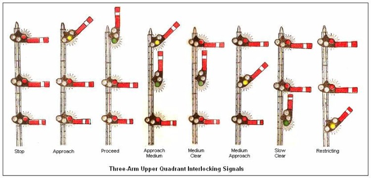
Interlocking signals were distinguished by a square-end blade and lights one above the other vertically. The names of the aspects are those that became standard later. The indication of the Approach aspect was: "Proceed at a speed reduced to not exceeding one-half the maximum authorized at the point involved (not exceeding thirty miles per hour) prepared to stop at the next signal." This wording was on a sticker pasted in later. In 1918, the requirement of reduction to medium speed was not included. Later, this was recognized as a good practice that would compel the engineman to take some action at the signal, reducing the danger of forgetting it. Approach Medium was called Approach Restricting, since "restricting" was then used on the NYC for what later was known as medium speed. The aspect called restricting in the diagram then had the indication "Proceed at Slow Speed, Prepared to Stop."
These aspects were exactly those later adopted for color-light signals, which gave the same aspects as the night aspects of the semaphores. Although some color-light signals had already been installed by the dates of these rule books, notably on the electrified lines in New York, both on the NYC and the Pennsylvania, which were often in dark tunnels, there was no mention of them in the rule books. They were, no doubt, explained in timetable special instructions. If the semaphore lamps were electrified, the lights could be as visible by day, effectively making them color-light signals. Some roads, such as the New Haven, actually used semaphores as color-light signals, reducing the blades to a minimum. Other roads lowered the height of the arms to engineman's-eye level (about 11 ft), as is done with color-light signals, to make them more visible against a dark background.
The three-arm signals express the philosophy of speed signaling in contrast with route signaling. The available routes are divided into three classes by the maximum speed allowed on them: normal-speed routes (usually without divergences), medium-speed routes (through high-speed turnouts), and low-speed routes. Often there would be only one normal-speed and one medium-speed route, but usually several slow-speed routes. The top arm is associated with the normal-speed routes, the middle arm with the medium-speed routes, and the shorter bottom arm with the low-speed routes.
With the earliest multi-arm signals, each arm governed a different route. Drivers were familiar with the routes, and knew the speed appropriate to each. The uppermost arm governed the leftmost divergence, the next arm the next leftmost, and so on. It was very unsatisfactory to have the main through route just somewhere in this stack of arms, so it was emphasized by a different shape of arm or by two lights (as on the Pennsylvania). A simplified arrangement was soon introduced, in which the top arm referred to the main route, the second arm to all the diverging routes, and the lowest arm to local, low-speed routes. From this, the idea of classifying routes by allowable speed and speed signalling was developed, which was adopted by the ARA in 1915.
It should be mentioned that the AT&SF used an even simpler system, in which the clear aspect of a three-position semaphore indicated that the main route was clear. An inclined arm and a yellow light governed all diverging routes, which were taken at restricted speed. Those roads retaining lower-quadrant arms also used three-arm signals at interlockings, the arms corresponding to proceed on main route, proceed on diverging routes, and proceed at restricted speed. Three-position arms allowed the display of Approach aspects as well as Proceed in each speed class.
 Procedures at non-interlocked railway crossings at grade were specified in timetable special instructions. Often, a stop was required by law at such crossings. The rule books illustrate three types of crossing signals: gate, ball and target. The gate displays a red board and red lamp. Gates are usually operated by train crews, and are still common, especially on secondary lines. The ball signal had a red ball, from which a red lamp was suspended. A raised ball generally allowed a train on a designated line to proceed, while a lowered ball permitted trains on the other line to proceed. Such a signal was used at Danville, Illinois as late as 1950.
The crossing target, or tilting target was invented on the Pittsburgh, Fort Wayne and Chicago before 1875 and became very common in the Midwest. It is not a "target", of course, though that inappropriate name became usual, but a semaphore by day and a position-light signal by night. The night aspects are displayed by lamps hung from the ends of the bar. These lamps could be raised and lowered from the ground without climbing a ladder. The color of the lamps is unimportant. Two aspects were usually used, as shown, though a third aspect with the bar vertical was also possible and sometimes used. The signal was erected in the angle between the lines so it could be seen from each. It had the great advantage that when movement was allowed on one line, it was automatically forbidden on the other. Timetable special instructions specified the interpretation of the aspects. Like the ball signal, it was usually operated by the telegraph operator at the station.
References
Rules of the New York Central and Hudson River Railroad Company Governing the Operation and Use of Interlocking, Block and Special Signals, effective February 1, 1912.
USRA, New York Central Railroad, Rules for the Government of the Operating Department, effective October 20, 1918.
R. B. Shaw, Down Brakes (London, P. R. Macmillan, Ltd., 1961). A very useful record of American railway accidents, even of those occurring before official reports to the ICC.
Return to Railways Index
Composed by J. B. Calvert
Created 10 December 2006
Last revised