Vacuum Tubes
This overgrown page covers all kinds of vacuum-tube electron devices, especially receiving tubes.
Many experiments are suggested, and much tube lore and curious circuits are presented. The Index may help you find what you want.
Index
- History and Theory of Thermionic Tubes
- Experiments
- Diodes
- The Noise Diode
- Phanotrons--Gas Diodes
- Triodes
- The Cascode Circuit
- Historic Triodes
- A Pliotron
- High-Frequency Triodes (acorn, etc)
- Power Triodes
- Screen-Grid Tetrodes
- Space-Charge-Grid Tetrodes; Low-Voltage Tubes
- Contact Potentials
- Pentodes
- Power Pentodes and Beam Power Tubes
- Battery Tubes
- Sub-Miniature Tubes
- 117V Heater Tubes
- Compactrons
- Grid Leak and Diode Detectors
- Oscillators and Mixers--Conversion
- Electron-Ray Tubes
- Voltage Regulator Tubes
- Thyratrons
- Other Tubes
- References and Links
Theory of Vacuum Tubes
Miniature vacuum tubes with cathodes of high-field-emitting carbon nanotubes are currently under study at Agere Systems in Murray Hill, NJ. A triode with amplification factor of 4 has been constructed, with an anode-cathode spacing of 220 μm, and a pentode is planned. Vacuum tubes may return to electronic technology! See Physics Today, July 2002, pp. 16-18.
 Devices in which a stream of electrons is controlled by electric and magnetic fields have many applications in electronics. Because a vacuum must be provided in the form of an evacuated enclosure in which the electrons can move without collisions with gas molecules, these devices were called vacuum tubes or electron tubes in the US, and thermionic valves in Britain. In 1883, Thomas Edison observed that a current flowed between the filament of an incandescent lamp and a plate in the vacuum near it (see figure at the right), when the plate was connected to the positive end of the filament, but not when the plate was connected to the negative side (the plate was actually between the two legs of the filament). No important application was made of this unexplained Edison Effect at the time. In 1899, J. J. Thomson showed that the current was due to a stream of negatively-charged particles, electrons, that could be guided by electric and magnetic fields. Fleming patented the diode in 1904 (B.P. 24850), where a filament and plate were arranged in the same envelope in a rather low vacuum, which could be used as a rectifier, or as a rather insensitive radio detector. In 1907, Lee de Forest patented the triode (which he called the Audion; the term "triode" was not used until much later, after it threated to become a trade name), in which a third electrode, the grid, was introduced to control the electron stream. This made a more sensitive detector, but the amplifying property was not used at first, and de Forest, who did not understand well what was going on, defended gassy tubes with their gas amplification. The introduction of high vacuum, as well as improved materials and processes, especially metal-to-glass seals, created a very useful amplifying device that allowed great developments in radio, telephony and sound reproduction. Schottky suggested a screen grid between the plate and control grid to make the electron tube useful at higher frequencies in 1919 (and actually made tubes with a second grid, but this was for space-charge control), but this was only realized by Hull and Williams in 1928 in radio receivers. The metal tube was introduced in 1935, but glass envelopes never disappeared and were constantly improved. The final pattern of electron tube was the "miniature" or all-glass type, which became the predominant receiving-type tube after about 1945. Transistors were invented in 1948, and in the next decade were improved to the point where they could take over most of the amplifying applications of electron tubes at much lower cost, and with greater reliability. Electron tubes remain in use as cathode-ray tubes, magnetrons, X-ray tubes, and for handling large powers. They were remarkable devices, using many sophisticated materials and processes, yet were widely available at low cost. We shall look here mainly at examples of receiving tubes, the smaller amplifying devices that have been completely replaced by semiconductors in current practice, but nevertheless will deepen our knowledge of electronics, while being fascinating to study. The name "receiving" comes from their use in radio receivers, their principal commercial application, but refers to all small vacuum tubes for general electronic purposes. For the cathode-ray tube and making your own oscilloscope, see The Cathode-Ray Tube.
The electrons move from the cathode (K), the negative electrode, to the anode or plate (P), the positive electrode. Conventional current is in the opposite direction. The electrons are liberated at the cathode by heat--thermionic emission--or as a result of bombardment by positive ions, which can cause emission of electrons or even heat the cathode the required amount for thermionic emission. All receiving tubes employ thermionic emission, though we will note certain examples of cold cathodes in special cases. These were not usually really cold, but heated by ion bombardment rather than by a current supplied externally. The space in which the electrons move is not completely devoid of gas, so some gas molecules may be ionized by collision with speedy electrons, when an electron is knocked off, leaving a positive ion. The positive ions move in the opposite direction to the electrons (but their current is in the same direction, since they are of opposite charge). The effect of positive ions in a receiving tube is very small, because of the very high vacuum that is used.
Self-heated electron emitters are called filaments. The carbon filaments of the Edison Effect were soon replaced by metallic emitters, usually tantalum or tungsten, which were used by Fleming and de Forest. In Germany, Arthur Wehnelt discovered in 1903 that barium or calcium oxides baked on a platinum base emitted copiously, and used these oxide-coated emitters on vacuum rectifiers evolved from discharge tubes, which he patented in 1904. However, the use of soft tubes, which contained residual gas, demanded the use of rugged tungsten filaments, which dominated in 1910-20. These filaments used low voltages and high currents, and had a short life because of the high temperatures required for adequate emission. Most radio sets had a rheostat to adjust the filament current properly. Wehnelt emitters would have been quickly destroyed by positive-ion bombardment in these tubes. Apparently by accident, thoriated tungsten wire was used in a trial at the GE factory in Harrison, NJ in 1920 on a UV201 tube. Thoriated tungsten gave 75 mA/W of filament power, while tungsten gave only 1.75. Thoriated-tungsten filaments became popular for receiving tubes, such as the UV201A, which was an improved UV201, around 1924. Its filament required 0.25 A at 5 V, while the UV201's had required 1.0 A. Since tubes were now all hard, or high-vacuum tubes, indirectly heated oxide-coated cathodes, which gave copious emission at low temperatures, were used almost exclusively in receiving tubes after 1930. Not only did these cathodes have a long life, but were also equipotential, making circuit design simpler. Thoriated tungsten remained for transmitting tubes, where a rugged emitter was necessary because of the higher plate voltages, but even here tungsten was the only suitable choice for really high voltages, to avoid damage from positive-ion bombardment.
The rate of emission of electrons from a heated metal is given by the Richardson-Dushman equation, i = AT2e-b/T A/cm2, where T is the absolute temperature in K, and A and b are constants typical of the emitter. For tungsten, A = 60 and b = 52,400K, while average values for an oxide cathode are A=0.01, b = 11,600. The exponential factor has by far the largest influence, so emission increases rapidly with temperature. This makes thermionic cathodes very suitable even for heavy currents. In all tubes, electrons are emitted in far greater numbers than required; most simply return to the cathode.
The electrons emitted by the thermionic cathode form a negative space charge cloud around the cathode, dense enough that if no electrons are removed by attraction to the anode, the rate of emission is equal to the rate of return. When the anode is made positive, some of the electrons are attracted to it out of the space-charge cloud, and a thermionic current results. The amount of this current is given by I = A V3/2, where V is the voltage from anode to cathode. This is called the Langmuir-Child law, and shows that electric field at the space charge produced by the anode controls the electron current. The cathode emits electrons copiously, so much that there are always enough electrons available to satisfy Langmuir-Child. Of course, at a sufficiently high anode voltage, the current may saturate, when all the emitted electrons are attracted to the anode, but this never occurs in normal operation, so small variations in cathode temperature have no effect. The current in a vacuum tube is said to be space-charge controlled.
If enough gas is present in the tube, the positive ions can counterbalance the negative electron space charge, robbing the anode of control and greatly increasing the current. Also, the positive ions can take over a large part of the electron emission at the cathode. Such tubes make efficient rectifiers, and the gas pressure can be quite low, as in some rectifiers, or rather high, as in a mercury-arc rectifier. In receiving tubes, positive ion collisions can destroy the delicate, high-efficiency cathode surface. Positive ions also cause small currents to negative electrodes that otherwise might be expected to carry no current at all. For all these reasons, receiving tubes have a high vacuum.
The electric field at the space charge that controls the current does not have to be created by the anode alone. A third electrode, the grid, is placed between the cathode and the anode, closer to the cathode. It is made of a spiral of fine wire, so electrons can pass through without hindrance. When it is made negative, it opposes the effect of the anode in creating an electric field, but does not attract any electrons, and so draws no current (except for the positive-ion current mentioned above). If it is made sufficiently negative, it can cut off the plate current entirely. If it is made positive, it can enhance the plate current, but then draws some grid current itself. The grid provides a sensitive control, using negligible power, of the large plate current, so the vacuum tube is a powerful amplifying device.
Early radio sets were battery-powered (domestic electrification was in its infancy, and absent in rural areas, when radio began), and a convention was established for identifying the batteries required. The filaments required low voltages at high currents (2W or more each), and their supply was called the A battery. The plates required high voltages at small currents, perhaps 90V at a few mA, and their supply was called the B battery. Grid bias was required, to hold the grids negative, demanding low voltages at small currents, and the corresponding battery was the C battery. The notations A and C were later little-used (except for actual battery radios), but the plate supppy came to be generally known as B+, and the letter B appears in subscripts of quantities referring to the plate circuit.
The cathodes of receiving tubes consist of a sleeve of nickel alloy coated with a compound of alkaline-earth oxides (Ba and Sr, usually). Inside is a tungsten heater wire insulated from the cathode with BeO or alundum (aluminum oxide) ceramic insulation. These cathodes must be heated only to about 850K (a dull red) to emit electrons in the amount necessary. Most receiving tubes require 6.3V or 12.6V for their heaters, at about 0.30A or 0.15A, respectively. Every tube type is identified by a type number, such as 6J5, where the first number indicates the heater voltage. 6 means 6.3V, 12 means 12.6V. Heaters are very forgiving of variations in voltage, but it is best to try to use the recommended voltages. AC is generally used, supplied from a small transformer. It is necessary to make sure that the difference in voltage between heater and cathode does not exceed 90V, so the heater AC supply should be grounded. It is usual to ground the center tap on the transformer for this purpose. Tubes for battery radios have plain filaments that are both heater and emitter, and must be supplied with DC. Their type numbers begin with "1" and are intended to be used with a standard dry cell of 1.5V. Larger tubes for high voltages have to use thoriated-tungsten filaments at 2000K,a bright yellow, to avoid damage from positive-ion bombardment, small as it may be. Heaters are sometimes called filaments, and the heater supply the filament supply, out of linguistic inertia.
Before the 1930's, each manufacturer used arbitrary designations for his tubes, and there was no uniformity or system. Tubes were first systematically identified in the U.S. by three-digit numbers, where the first digit denoted the manufacturer. For example, a type x10 was a power triode, a type x36 a screen-grid tetrode, where x was the manufacturer's number (usually omitted). Later, a new system was introduced where the first digit gave the filament or heater voltage, and the last digit gave the number of functional electrodes. This scheme was introduced by the RMA (Radio Manufacturer's Association) in 1934. A letter between these digits was assigned in order of introduction. For example, a 2A3 was a power triode with a 2.5 V filament (this popular tube is, remarkably, still in use for hi-fi amplifiers because of its low distortion!). This system was not comprehensive enough, and in the final system, the first number designated the heater voltage, but the remainder of the designation was arbitrary. Filaments were customarily used, especially in power and rectifier tubes, because they gave more current per watt of heating power. The indirectly heated, equipotential cathode that could be supplied by AC rather than by battery power was widely used after 1930.
A tube with just cathode and anode is called a diode, a term that has survived into the semiconductor age. Diodes were used for power or signal rectification, just like their semiconductor relatives. A "full-wave" diode has two anodes. When a control grid is provided, the tube is called a triode, and is used for amplification. Let's first study the peculiar circuit behavior of triodes, which will lead us to the reason for the addition of more grids, and the creation of the pentode, which turns out to act very much like a transistor.
 Circuit symbols for a triode are shown at the right, and other tube symbols are derived from it. The connections are plate P, grid G, and cathode K or filament F, F'. These are analogous to the collector, base and emitter of a transistor, with the same polarities and direction of current flow as an NPN transistor. The circle is a part of the symbol. Grid connections can be to the right or left of the symbol, as convenient. A gas tube is indicated by a dot in the lower right-hand part of the circle. The heater of an indirectly heated cathode is usually not shown. A cold cathode (operating by positive-ion bombardment) is shown as a small circle. There are examples of these symbols below.
The important variables are the independent variables Vp and Vg, the plate and grid voltages (with respect to the cathode), and the dependent variable Ip, the plate current. A plot of Ip against Vp for a fixed value of Vg is called a plate characteristic, and a plot of Ib against Vg for a fixed value of Vp is called a transfer characteristic. From a family of either characteristics, the complete circuit behavior of the tube can be predicted. Unlike transistors, tubes of different types can have quite different (though similar) characteristics, so characteristic curves are much more important.
 Let's begin with idealized plate characteristics for a triode, shown at the right. These are curved lines, but we represent them by straight lines for ease of understanding the various slopes and distances involved, which will be constant. Actual characteristics are not really far from straight lines, anyway. There is one curve for each grid voltage represented, which differ by a constant amount, here 2V. The horizontal distance between them, represented by the line labelled μ, is the amount the plate voltage must increase to hold the plate current constant; it represents the relative influence of plate and grid on plate current, and is the amplification factor. The vertical distance between them shows how much the plate current changes for a change in grid voltage. The ratio is a conductance, called the transconductance, denoted by gm, measured in siemens (mho). The slope of the curves is the ratio gm/μ, called the plate conductance gp. With vacuum tubes, the reciprocal rp was always used, called the plate resistance. Since actual characteristics are curved, these quantities vary for different currents and voltages.
What we desire to represent is a function of two independent variables Ip(Vp,Vg), which can be represented as a surface in three dimensions. Our various characteristic curves are orthogonal views along one or another of the axes. There are three such views possible, each directly related to one of the three parameters, of which we generally use only two, the ones mentioned here.
A vacuum tube carrying a current I with a plate voltage V dissipates power VI, just as if it were a resistor. However, the process is different. In a resistor, an electron gives up small amounts of energy to the lattice as it is accelerated and then is scattered. In a vacuum tube, the electron acquires a kinetic energy as it is accelerated, which it gives up all at once when it collides with the plate. It is not really correct to ascribe this to the "plate resistance," as some texts do, which is an incremental ratio. Since the plate is in a vacuum, the resulting heat can only be radiated or conducted down the supports. Much of the radiated heat is infrared, which is absorbed by the glass tube envelope. Note how plates are blackened to raise their emissivity and often provided with fins. Really large tubes had plates externally exposed capable of air or water cooling with elaborate seals to the glass parts. Plate dissipation is always a limiting factor in power applications.
The line marked load line shows the difference between the supply voltage Vbb and the voltage drop in a resistance RL in series with the tube at any plate current, giving the plate voltage directly. The series resistance is mainly a plate resistor, but if there is a cathode resistor (for purposes of biasing) it should be included. There are generally different load lines for static (DC) and dynamic (AC) operation. As the grid voltage is varied, the plate current and voltage vary along the load line. The quiescent or operating point can be selected at some point along the DC load line, and so the DC grid bias can be found. This grid bias can be obtained from a C battery or equivalent, or from a cathode resistor, just as an emitter resistor is used with a transistor.
A cathode bias resistor is often bypassed by a capacitor if its negative feedback effect is not desired in dynamic operation. The reactance of the capacitor at the lower corner frequency should be equal to the resistance looking into the cathode (normally 1/gm in parallel with the cathode resistor). The size of the cathode resistor has only a small effect on the size of the bypass capacitor. The capacitor never has a large voltage across it, and can be a low-voltage electrolytic. Only part of the cathode resistor can be bypassed if some feedback is desired.
A typical triode, of which the 6J5 is chosen here as the example, has a μ = 20, rp = 6.7k and gm = 3.0 mS. Of course, the relation μ = gpmp always holds. The value of transconductance may seem small, compared to a transistor, but it should be remembered that it refers to a high-voltage plate circuit, and that the input impedance is infinite, so the power amplification is extremely large. The 6J5 is called a "medium-mu" triode. The similar 6SL7, a "high mu" triode, has μ = 70, rp = 44k and gm = 1.6 mS. The 6SL7 is a dual triode, two independent valves sharing the same heater. The dual version of the 6J5 is the 6SN7.
The maximum plate voltage of the 6J5 is 300V, and the maximum plate current is 20 mA. Its maximum plate dissipation is 2.5W (product of average plate current and average plate voltage). This gives an idea of the ratings of receiving tubes used as voltage amplifiers. As power amplifiers, the allowable plate currents can be quite a bit larger, and hundreds of watts output is possible with relatively small tubes. The interelectrode capacitances of the 6J5 are on the order of 3.4 pF, and are significant at high frequencies.
 The small-signal equivalent circuits for the triode are shown at the right. The Norton source circuit is exactly the one for the FET. In the case of the triode, the plate resistance is always important, and cannot be neglected. The other circuit is just the Thévenin source corresponding to the Norton source. It shows the significance of the amplification factor, and is useful for triodes because of the rather small plate resistance. We did not find the Th%eacute;venin source for transistors very useful, and did not introduce a parameter analagous to the amplification factor for this reason.
It's easy to see that the maximum voltage gain achievable with a triode is μ, if the load resistance is much higher than the plate resistance. The rule we derived for the gain of a transistor amplifier as the ratio of the collector and emitter resistances holds here as well, expressed by μ = gmrp. The quantity analogous to re is 1/gm, which is 333Ω for the 6J5. Mu is a rather modest number, so triodes are not good for high voltage gain. They make very good power amplifiers, however, since large currents can be controlled. Using the Thévenin source, the gain of a usual common-cathode amplifier (analogous to a common-emitter amplifier) is simply a voltage divider problem. There must be a plate resistor in series with the plate, or else the voltage would never change, but it should be as large as possible, and has only a small effect on the gain. We shall examine these circuits in detail in the experiments, but this provides the background.
In order to provide higher voltage gain, the plate resistance must be reduced somehow. We recall that with a transistor, the analogous collector resistance was very large, and there was no problem with voltage gain. The plate resistance is the result of the effect of plate voltage on the space charge. This effect is not necessary for control, which is provided by the control grid, so what we need is to eliminate the effect of the plate voltage on the space charge. This is done by introducing another grid, the screen grid between the control grid and the plate. If this grid is held at a constant potential, the space charge is "screened" from the effects of changes in plate voltage. The screen grid is usually bypassed to ground by a capacitor, whose reactance at the lower corner frequency should be smaller than the resistance connecting the screen grid to B+. Some, but few, electrons are removed by the screen grid, since it is again a coil of fine wire. With this change, the plate characteristics become (nearly) horizontal lines, as for the transistor, and the plate resistance becomes large, approaching a megohm. The resulting tube is called a screen-grid tetrode.
Although tetrodes worked as expected, they had a serious defect. It happens that speedy electrons colliding with the plate knock out secondary electrons. In a triode, these are rapidly sucked back to the positive plate, and the same happened in a tetrode when the plate potential was higher than the screen grid potential. In normal operation however, especially with large voltage gain, the plate voltage has a large swing, and can become less positive than the screen grid. Now all these secondary electrons (and some of the primary ones, too) are attracted to the screen grid, and there is a definite sag in the characteristic in this region. To prevent this, it is necessary to establish an electric field at the plate that is always directed toward the plate, to suppress the escape of secondary electrons. This is provided by a third grid, the suppressor grid, which is usually connected to the cathode. The tube with three grids: control, screen and suppressor, or grids 1, 2 and 3, is called a pentode, which turns out to be a superior voltage amplifier, fully equivalent to a transistor. A typical small pentode, the 6SJ7, has a plate resistance of over a megohm, and a transconductance of 1.6 mS.
An ingenious modification of the pentode has electrodes that shape and concentrate the electron beam instead of a suppressor grid, the negative space charge of the electrons doing the same work. These are called beam power tubes, and were good for power work, as the name indicates. A typical example, the 6L6, had a transconductance as high as 6.0 mS, and the smaller 6V6 about 4.0 mS. Both types were widely used for high-fidelity audio amplifiers, and tube amplifiers still have proponents. The same tubes were used in small amateur radio transmitters, which shows the versatility of vacuum tubes.
Receiving pentodes were also classified as sharp cutoff or remote cutoff, an example of designing tubes to fit their applications. A remote cutoff pentode had a grid with variable spacing, so that areas of wider spacing let electrons through when the grid was made more negative, when areas of smaller spacing were cut off. This effectively reduced the transconductance of the tube, decreasing its gain in response to increased negative grid bias, which was used for AGC (automatic gain control) in IF amplifiers. The 6SK7 was a very popular remote cutoff pentode used as an RF and IF amplifier. The 6SJ7, on the other hand, was a sharp-cutoff pentode, used as an audio voltage amplifier. The amplification factor has little significance with pentodes, as with transistors, and transconductance is the important parameter. The screen grid also acted as an electrostatic shield between control grid and plate, reducing the Miller capacitance to extremely small values, 0.003 pF in the 6SK7. If the screen and suppressor grid are connected to the plate, the pentode operates as a triode.
A very curious and ingenious kind of tube was the electron-ray tube, used on receivers to give a visual indication of the accuracy of tuning to a station. Don't confuse it with the cathode-ray tube that uses a guided electron beam for oscilloscopes and TV receivers. It showed a luminous disk, with a dark sector. The dark sector was made as small as possible to achieve accurate tuning. It worked from the AGC (automatic gain control) voltage of the receiver. This is a feedback signal that tries to keep the signal amplitude constant at the output of the intermediate frequency amplifiers, increasing the gain for weak signals and decreasing it for strong. It is usually a negative voltage produced by rectifying the IF output. The tube has a thermionic cathode and a conical anode or target covered with cathodoluminescent phosphor (like a CRT), which glows from the 3 or 4 mA of plate current that flows when it is across 125V or more (up to 250). Control electrodes, of which there are two on opposite sides of the 6AF6, make two dark sectors that are widest when at 0V, and narrow as the control voltage approaches the target voltage. The control voltage is typically provided by the plate of a triode controlled by the AVC, such that full negative AVC cuts off the triode and makes the sector as small as possible. All this was cheaper and more graphic than a pointer meter.
Another kind of tube that we'll look at here is the glow-tube voltage regulator. The voltage across a glow discharge depends on the gas and the cathode material, and is almost idependent of the current through the discharge in the "normal glow" region, in which the glow does not completely cover the cathode, and expands to accommodate more current. Tubes were manufactured for voltages of 75, 90, 105 and 150 that were used like Zener diodes, handling from 5 to 40 mA. There is more information on glow discharges in Relaxation Oscillators, and on Zeners in Voltage Regulators. VR tubes are treated here because of their association with vacuum tubes, and the higher voltages involved.
Experiments
Vacuum tubes generally operate at higher voltages than transistor circuits. Like transistors, vacuum tubes are happier at higher voltages, which for receiving-type tubes, typically would be, say, 200 to 250V. It was once quite common to make DC power supplies for such voltages, using a transformer with a center-tapped secondary (say 200-0-200V), and a rectifier with double anodes and a common cathode, feeding a filter consisting of capacitors of 8 or 16 μF, and a choke of 10 H or so. It was not convenient to make a bridge rectifier with vacuum diodes (three separate filament transformers are necessary), so full-wave rectification with a center-tapped secondary was usual. These days it is rather difficult (and expensive) to acquire all these things, with the possible exception of the capacitors, which are now available up to millifarads at voltages up to 450 V.
The voltages normally used with receiving tubes are not high enough to be really dangerous, though a shock will not improve your day. If you are eager for new experiences, I can save you the trouble of finding out by saying that a DC shock is kind of like a hammer blow, not the zap of an AC shock, and does not paralyze, as an AC shock does. Shocks are given by current, not simple contact, so a good and old rule is to work with one hand in your pocket around high voltage. Always turn things off before making any adjustments or changes, of course, and be neat. Avoid touching bare metal. With these precautions and normal care, you will be fine. The solderless breadboard, DMM and oscilloscope can handle these voltages quite well. All the usual resistors and potentiometers are not afraid of 150V, so long as power ratings are observed. 1W and 1/2W resistors may be required in some places. Capacitors must be able to stand the voltages across them; many of those used with transistors will not be adequate. Keep a separate kit of capacitors rated at 100 V and above for this work. High-voltage capacitors are not needed everywhere, only in the plate circuits and for coupling from plate circuits.
 The circuit of the laboratory B+ supply that I use for vacuum tubes is shown at the right, and the supply itself is shown in the photograph below. It provides a regulated variable 60-150 V output, and a regulated fixed voltage output (for screen supply) created by a VR tube. VR tubes can be exchanged for different voltages. The MagneTek N-51X 115 V-115 V isolation transformer is available from Antique Electronics (see references), and a cheaper one from All Electronics. The transformer secondary has a DC resistance of 22Ω, which limits the surge current satisfactorily without having to add a series resistor. By no means eliminate the isolation transformer and use the 120 V household supply directly, because of the ground hazard. A variable transformer (Variac) is an autotransformer that does not isolate the output from the power line ground. I earnestly recommend that you do not work on AC circuits without isolating them from the service ground. The 110/220 adapters commonly available in 50W and 300W sizes, used for shavers and other small loads, should not be used, since they are autotransformers and do not provide isolation. They are, in fact, quite dangerous things, and should be used with great care. The supply was built in a 5" x 7" x 3" aluminum box, with an octal socket for the VR tube on top. The socket can be left vacant when the fixed voltage output is not required.
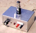 The voltage regulator requires a certain minimum current (about 5 mA) to function properly. If you are only drawing a few milliamperes from the supply, connect a 12k bleeder resistor across the output. Otherwise, the regulator will not adjust down to the lower voltages. Or, 220Ω and 10k fixed resistors, and a 15k pot, could be used at the voltage regulator, which would draw the necessary minimum current. The VR tube can be replaced by a high-voltage Zener diode.
A 25W isolation transformer is available at the date of writing from All Electronics (See the Your Laboratory page for a link) for $4.50. This transformer is surplus from the Power One firm, and is an excellent value. Solder a jumper between tabs 1 and 3, and another between tabs 2 and 4. The 120V input is connected between 1-3 and 2-4. The output tabs are marked B. This transformer would work well in the circuit above, or it could be put in a box and wired with line cord and output receptacle as a general isolation transformer. It should supply 200 mA without trouble, ample for our purposes.
 An idea for an inexpensive B+ supply is shown at the right. The greatest expense is for the capacitors, which will cost about $15. It is based on a half-wave voltage doubler, and gives 300V for a 115V rms input. It cannot supply large currents, but is perfectly satisfactory for anything but power amplifiers. If supplied from a variable transformer, it becomes a variable supply for all voltages from 0 to 300. Note very carefully that one side of the supply is connected to the AC line, and this must be the grounded side, for your safety, and to avoid ground loops. You cannot ground the positive terminal of this supply to get a negative voltage supply (for use as a C supply, for instance). An isolation transformer, if you have one, would eliminate this hazard. If you don't have an isolation transformer, use a polarized plug to guarantee that the white wire is connected to the circuit ground. If you have a good ground, consider the old trick of connecting only one wire in the power cord, and using the ground to complete the circuit. It is best to observe the power ratings of the resistors and the voltage ratings of the capacitors. This circuit has been tested, except for the fuse. If the 0.5A slow-blow fuse fails, try a 1.0A. This fuse is to turn things off if a capacitor fails; nothing valuable is protected here, but it saves mess.
 The RC ripple filter is worth the expense. Waveforms are shown at the left. The waveform at node "a" is the familiar one for a "tank" capacitor, and the ripple is fairly large. Since the impedance of a 100 μF capacitor is only 26Ω at 60 Hz, the ripple is reduced by a factor of almost 25. At 300V output and a load of 12 mA, the ripple is less than 0.1V, a very satisfactory result. Note that all that is left in the ripple is the 60 Hz component. The filter would work even better on a full-wave rectifier, but here it is very satisfactory, better and more economical than larger capacitors. Of course, a filter choke could be used for an even better result and less voltage drop, but this would double the cost of the supply.
You will also need a heater transformer, which can be quite small if supplying only one tube that requires 0.3A. The transformer can be put in a box with an on-off switch and convenient terminals. Ground the heater supply (at a center tap if one is provided) to the B+ ground, to avoid excess voltages between heater and cathode. If you have a 12.6V CT (center-tapped) secondary, you can supply both 6.3 and 12.6 V heaters. Many 12.6V miniature tubes can also be connected for 6.3V. Tubes whose designations begin with "1" have filaments that can be supplied from a single D cell. Obtain a holder for the cell so connections are easy. 6.3 V was chosen to be compatible with 6 V car batteries, but the supply is usually AC. Many rectifier diodes use a 5 V filament or heater supply, apparently for historical reasons.
A "C" supply, for the grid bias in measuring characteristics, can be any isolated low-voltage supply of say, 15V, and a potentiometer can be used to pick off a variable voltage, since little current is involved. A separate high-voltage supply for screen grids may also be convenient, though it is easy to pick off the necessary voltages with a Zener or a VR tube from the main B+ supply. This cannot be done, of course, if the B+ voltage is adjusted using a variable transformer.
An all-in-one economical supply for vacuum-tube measurements is shown below. It uses an inexpensive isolation transformer from All Electronics, and can be made for about $30.00. The most expensive single part is the aluminum chassis. The grid potentiometer could be a precision 10-turn pot, but this would be expensive, and an ordinary carbon or plastic potentiometer (1/2 W or better) will be satisfactory. The maximum plate voltage of 120V and maximum plate current of 35 mA is adequate for many measurements. If you use a three-wire line cord, ground the chassis to the green wire. If you use only a two-wire line cord, it is probably better not to ground the chassis.
 Vacuum tubes come with metal or glass envelopes, and in latter days with either the familiar octal arrangment of 8 pins, or as miniature glass tubes with 7 or 9 pins. There were earlier bases with four, five or six pins. Later, 12-pin miniature "compactron" or "duodecal" tubes were used in TV sets. Miniature tubes were not miniature, simply tubes with a button seal and all-glass envelope closely fitting a normal-sized cage. Subminiature tubes were actually miniature. Sometimes connections to grid, plate or (rarely) cathode were made to caps at the top of the tubes. In small tubes, these caps have a diameter of 1/4". The pins are numbered consectively clockwise, starting from the left of the index key for the octal, or to the left of the wider space, for the miniature, always looking at the bottom of the tube. This is shown for the octal base at the left. Pin numbers are given in the circuit schematics here. Most sockets have pin numbers marked. You will need to get sockets for the tubes you study, one for each type of socket. Solder wires to the tab at each pin that can be inserted in the solderless breadboard. I use the resistor color code for the pin numbers. A convenient octal socket fixture is available that comes with screw terminals for making connections. It was intended for relays, but is very useful for tube experiments. Heater connections for octal tubes are typically (not always!) to pins 2 and 7, and often to pins 3-4 on 7-pin, or 4-5 on 9-pin, miniature tubes. Sometimes halves of the heater can be connected in series or parallel, for two different voltages. Sockets were originally mounted in holes punched in aluminum chassis, secured by locking rings or by screws and nuts with a mounting plate. The chassis was, not surprisingly, the ground or common.
The "Loktal" tube was an excellent idea that was never universally adopted, mainly because miniature tubes took over in the 1950's. Since loktal was a trade name, RCA used "lock-in" instead, and you sometimes see "loctal." The loktal tube has an 8-pin button-seal (like the seal on miniature and octal GTB tubes). A natural metal base (of some aluminum alloy, apparently) shields the base of the tube and has a central pin with a circumferential locking groove. The pins project only 6 mm, and are 1.4 mm in diameter, much smaller than octal pins, so the locking action guarantees that the tube will stay in the socket in spite of the small pins. The tubes are roughly the same size as an octal GT tube. Most are one size, but a few power tubes have a slightly longer envelope. There are no grid caps on any Loktal tube, and the heater connections are always to pins 1 and 8. Among the thoughtful features of loktal design, the type number appears in a hexagon on the top of the tube where it is visible from above, not on the side as on octal tubes. There is a dimple on the base corresponding to the key of the central pin, making the tube easy to orient for insertion. It seems that a lot of getter was used, so the tops of the envelope appear heavily silvered. The available types are only those used in AM and FM receivers. There are, nevertheless, enough types for a broad variety of experiments, and the prices are not excessive, so you may want to standardize on Loktals. Type numbers beginning with 7 have 6.3 V heaters, while type numbers beginning with 14 have 12.6 V heaters. There are some 7xx and 14xx tubes that are not Loktal, and some tubes that actually take a 7 V heater supply. One loktal rectifier, the 5AZ4 (a 5Y3 equivalent), has a 5 V filament. Loktal tubes designed specifically for battery-powered equipment had 1.4V filaments. The type numbers began with "1L." There were also rectifier and beam power loktals with 35, 50 and 70-volt heaters for AC/DC sets with series heater connections.
A tube designated simply 6N7 will be a metal-envelope octal tube with a 6.3V heater. A 6N7GT will have a cylindrical glass envelope. A 6N7G would have a shouldered glass envelope of the graceful shape designated ST. The electrical characteristics of such tubes were the same, whatever the envelope shape.
A very important part of vacuum-tube technology was bringing the metal leads through the glass envelope. Coefficients of expansion must be exactly matched, and the seal must be strong. Originally, tubes had bases (usually Bakelite) to support the contact pins mechanically, taking the strain off the pressed-glass seal, which was made of lead glass. Around 1935, the metal envelope was developed, but there was still a base. The all-glass "miniature" tube was made possible by the "button seal" that supported the contact pins mechanically as well as bringing them through the glass, allowing the base to be eliminated and tube size to be reduced. The insides, or "cage," was the same size as in previous tubes, however. It is supported on its leads, which are welded to the contact pins before the envelope is fused in place and evacuated. The button seal is also used, in a larger form, on tubes designated by GB at the end of the type designation, and by Loktals. The final step in manufacture was "flashing" the getter, usually barium or magnesium, to perfect the vacuum by adsorption of any remaining gases, leaving a shiny coating. This was generally done by heating a loop inductively by RF from outside.
Diodes
 Thermionic diodes, like semiconductor diodes, are divided into signal diodes that handle small currents at low voltages, and rectifier diodes that handle large currents, often with large inverse voltages. A diode has an electron-emitting cathode and an electron-receiving anode or plate. The arrangments of cathodes and plates in commercial tubes, and what they are called, are shown in the figure. Signal diodes are also often added to a triode or pentode, sharing the same cathode and with one or two plates. Current flows only from plate to cathode, and this unidirectional conduction is the purpose of a diode. Diodes cannot amplify.
Signal diodes always have indirectly-heated cathodes, so they are easy to use. It is only necessary to make sure that the heater-cathode voltage does not exceed specified limits, usually a few hundred volts. Rectifier diodes often have filamentary oxide-coated cathodes, since these cathodes are more efficient when large currents are needed, requiring less power. We are considering only vacuum diodes, kenotrons, in this section. Thermionic gas diodes, or phanotrons, will be treated below, since they have rather different properties.
Thermionic diodes have now been completely superseded by semiconductor diodes, largely for economic reasons, physical size and the need for a filament supply. A silicon diode capable of carrying 1 A is available for $0.04 or so, and takes up very little room. However, diodes can teach us a lot about thermionic emission and other interesting things. They do work rather well, and it is good to make their acquaintance.
The forward voltage (in the direction of current flow) of a diode is always relatively low, less than 15 V or so. The plate current is roughly proportional to the 3/2 power of the anode-cathode voltage (Langmuir-Child law), and the proportionality factor is called the perveance. The perveance depends on the geometry of the tube, increasing with larger area and closer spacing. It's remarkable that most diodes agree with Langmuir-Childs so well, in spite of different geometries. Since the voltages are low, contact potentials may affect your measurements. Contact potentials are discussed below in the section on low-voltage tubes. The easiest way to find the perveance is to plot I2/3 against V, and to draw the best straight line. The intercept gives the value of the "true" zero plate voltage, and the slope, raised to the 3/2 power, is the perveance. Perveances range from 0.02 to 2.4 mA/V3/2 for a representative assortment of 12 diodes of all types. There is no turn-on voltage drop for a thermionic diode, as there is for a silicon diode. Conduction begins immediately when the plate is positive with respect to the cathode, and stops immediately when the plate goes negative. It is easy to measure the V-I characteristic of a diode with a low-voltage DC supply, a voltmeter and an ammeter. I use a 100Ω resistor in series to make adjustment easier and safer. Thermionic diodes are not as easy to destroy as semiconductor diodes, and will take a good deal of abuse.
 The 6AL5 dual diode, whose basing is shown at the right (7-pin miniature socket), is a typical signal diode. IS is an internal shield between the diodes. The two diodes and the shield are easily seen through the glass envelope, and you should notice how close the plates are to the cathodes. The close spacing means a large perveance, so only small plate voltages are required. Don't connect this tube directly across high voltages! A peak inverse voltage of 330 V can be resisted, and the DC plate current should not exceed 9 mA. Peak currents can go up to 45 mA if necessary, however. I measured the perveance as 2.42 mA/V1.5, for one plate, a large value. The 6AL5 gives 9 mA with a plate voltage of only about 2.5 V! The heater, connected to H-H, pins 3 and 4, takes 0.3 A at 6.3 V.
 Try the 6AL5 in the circuit shown at the left, which is a basic signal rectifier with a 4.7k load resistor. Feed it with the signal generator, and compare the output and input with the oscilloscope. Try input peak-to-peak voltages of only 2 V or so. You will notice that there is no "diode drop" with the 6AL5--it acts like a perfect diode, rectifying down to small voltages. We know how to do this with a semiconductor diode and an op-amp, but here it's done quite simply. The 6AL5 has an incremental resistance of only about 237 Ω, and is nearly linear. It is easy to run a plate voltage versus plate current curve with a low-voltage power supply. Keep the load resistor, and subtract the voltages at plate and cathode to find the plate voltage.
The 6H6 is an octal dual signal diode like the 6AL5, in a unique small metal envelope. The heater is connected to pins 2-7, the cathodes to 4 and 8, the plates to 3 and 5. 3 and 4 are one diode, 8 and 5 the other, and completely independent. It can be used for any reasonable service, such as AM detection, as a full-wave rectifier, or as a voltage doubler, so long as the current per plate is 8 mA or lower, and inverse voltages do not exceed 420 V. The voltage between heater and cathodes should not exceed 330 V. Measure the plate current as a function of the plate voltage up to 10 mA (the plate voltage will be about 7 V), and plot the current against the 3/2 power of the voltage. I obtained a rather straight line, showing agreement with Langmuir-Child, with a permeance of 0.5 mA/V1.5. At 8 mA, the incremental resistance was 590Ω, and V/I = 785Ω. The 12H6 and 7H6 are similar tubes with different heater ratings and basing.
The 7Y4 is a typical small full-wave rectifier with an indirectly-heated cathode, like the more common 6X4 (miniature) and 6X5 (octal). This "Loktal" tube is inexpensive. Many of the common rectifier diodes are rather costly, for the curious reasons associated with the current tube market. The heater, taking 6.3V at 0.5A, is connected to pins 1-8 (as with all Loktal tubes). The cathode is pin 7, and the plates are pins 3 and 6. The peak inverse voltage is 1250 V, the peak current 180 mA, and the average dc current 70 mA. The heater-cathode voltage should not exceed 450 V. Measure the plate voltage for currents up to, say, 50 mA, and plot the results as for the 6H6. Again, we find a straight line and a perveance of 0.58 mA/V1.5. Note that the plate voltage varies considerably as the current changes, from 4 V at 7 mA, to 16 V at 40 mA. Compare these voltages with those for a mercury-vapor phanotron as discussed in the next section. The 7Z4 is a somewhat larger full-wave rectifier (with perveance 0.40), the Loktal equivalent to the types 80 or 5Y3 that are now much more expensive.
 An excellent diode for observing the Langmuir-Child law is the 2X2A. This tube has a 4-pin base like the 82 phanotron discussed below, and the large, bell-like anode is brought out to a cap at the top of the ST envelope. The oxide-coated cathode thimble is easily seen. The heater takes 2.5V at 1.75A, so it can use the same transformer as the type 82. The rated DC current is 7.5 mA, and the maximum voltage is 4500V. A plate voltage of about 60V is needed to reach 7.5 mA plate current, so measurements can be made over a wide range of voltages. Plot your results as I2/3 vs. V. A straight line will be found, that intercepts the V axis at -1.2V. The perveance of the 2X2 is found to be 0.0165 mA/V3/2. The unusually low value is due to the large cathode-anode spacing.
The 6V3-A is a strange miniature tube with a cap on top that is the cathode connection. Its heater, connected to pins 4 and 5 of the 9-pin miniature base, takes 1.75 A at 6.3 V. The plate is connected to pins 2, 7 and 9. This tube is designed for the rugged service of a television damper diode. During horizontal retrace, the damper diode conducts, charging the boost capacitor while absorbing the large inductive kick. The peak inverse voltage is 6000 V, the peak current 800 mA, and the average current 135 mA. The large-diameter cathode tube and long plate imply a large perveance, which, in fact, is about 2.3 mA/V1.5. This tube happens to be very cheap, but would serve as an excellent half-wave rectifier for practically any purpose. There are other damper diodes, such as the 6W4 and the 6AX4GT (perveance 1.42), that would have similar characteristics.
As an example of the small signal diodes that are often combined with a triode or pentode in the same envelope, and share the same cathode, the 6AV6 or 6AT6 furnish good examples. The 6AV6 has its heater at pins 3-4, cathode at pin 2, and the signal diode plates at pins 5 and 6. The maximum current for each diode is 1 mA. I connected the two plates together for measurement, and took the current up to 3 mA, for which a plate voltage of 6.4 V was required. The curve of I against V1.5 sagged a little at low currents, but the upper part was quite linear, showing a perveance of 0.085 mA/V1.5 for one plate. The incremental resistance was 4.55kΩ, and V/I was 5.05kΩ at 1 mA. The current for one plate obeyed the formula I = 0.15 + 0.085V1.5 mA. In this tube (and similar ones) the plates are flat, one on each side of the cathode.
The 1A3 seems to be the smallest signal diode of all. It was designed for portable measuring apparatus. The heater takes 0.15A at 1.4V (a D cell), connected to pins 1 and 7 of the 7-pin miniature envelope. The cathode is at pin 3, the anode at pins 2 and 6. The peak inverse voltage is 330V max., the maximum plate current 5 mA, and the average plate current 0.5 mA DC. Maximum heater-cathode potential is 140V. The anode is only a few millimeters high; most of the envelope contains only vacuum. The measured perveance was 0.075 mA/V1.5.
The Noise Diode
A special kind of diode should be mentioned here, because experiments with it are quite interesting. It is the noise diode, intended for the specific purpose of producing wide-band RF noise through the shot effect. Shot effect noise is fluctuations in the anode current due to the random collection of electrons. We have already mentioned that the anode current is controlled by the space charge around the filament. It was discovered, to some surprise, that this correlated successive electrons so that they were emitted regularly to maintain a constant current, and therefore the shot effect was nearly completely eliminated. That is, a normal diode has no shot effect noise in its plate current.
The noise diode is designed so that at reasonable plate voltages, all electrons emitted by the filament are immediately drawn to the plate without forming much of a space charge. Since the electrons are emitted randomly, the anode current will show the full shot effect noise. This is done by purposely making the filament to have low emission. To do this, a tungsten filament is used. Noise diodes give us the opportunity to observe a tungsten filament, as well as temperature saturation.
 An available noise diode is the 5722, whose basing is shown at the right. The 7-pin miniature tube was made as late as 1977, and now costs about $14, which is probably not much more than when it was new. The maximum plate voltage is given as 200 V, and the maximum plate current as 35 mA, so apparently the plate can dissipate 7 W. The plate has wings that make a good dissipation probable.
 A circuit for testing the 5722 is shown at the left. Note that an RF choke is put in the plate lead to act as a load for the current fluctuations. This choke should be rated for the plate current employed. I connected a variable DC supply to the filament as shown, to pins 3 and 4, leaving the center tap alone. This supply should be rated at 2 A or more. Increase the filament voltage gradually, looking for the glow. There will be no plate current until the filament current reaches about 1.3 A, but it increases very rapidly beyond this point. The filament glows brilliantly, like an incandescent lamp, since its operating temperature is about 2400K, not the 900K of an oxide-coated filament. The filament current should not be allowed to exceed 1.6 A. If the power supply has current limiting, it can be useful here. By setting the plate voltage at near 200 V, you can see the saturation current as a function of filament current.
For two or more reasonable values of the saturation current, say 5 mA, 12 mA and 20 mA, record the current as a function of plate voltage and plot your results. For If = 1.5 A, the plate current saturated for about 50 V on the plate, approaching a value of about 12 mA. It is easy to find out what plate voltage to use to ensure saturation when making shot noise in this way. It is very difficult to make noise measurements in the usual breadboarding environment. I thought it just possible to have seen some on my 100 MHz scope with a plate current of 20 mA, without amplification. See the page on Noise for more discussion of noise measurements.
The Phanotron
General Electric and Westinghouse liked to coin names for their products that drew on Greek. A phanotron (fanos, "bright") was a gas-filled thermionic diode, while a kenotron (kenos, "empty") was its vacuum cousin, which we have just been studying. All these tubes, once so common and useful, have been totally replaced by the much cheaper and smaller semiconductor diode. There is still, however, quite a lot of interesting physics and electronic involved with gas tubes, which makes their study profitable.
The most convenient phanotron to study is the type 82. Its kenotron cousin is the very familiar type 80, later available as the 5Y3, which is still, remarkably, in production. In the curious contemporary tube market, these are rather expensive, and the 82 was not cheap. Both are full-wave rectifiers with two plates and filamentary cathodes. The 80 and 82 have a 4-pin base, once rather common,and the graceful ST shouldered glass envelope. When you pick up an 82, the droplets of mercury on the inside of the envelope will be evident. There are two cylindrical plates, with an oxide-coated filament ribbon in an upside-down V inside each.
The filaments will glow orange when you apply the 2.5V at 3A they require across the larger pins 1 and 4. The plates are connected to pins 2 and 3. A low dc voltage can be applied between plate and cathode, using perhaps a 100Ω resistor in series to soak up extra voltage. Some current will flow even at low voltages as the plate attracts electrons from the cathode space charge. When you raise the voltage, it will stabilize at about 12 V and a bright blue glow will fill the plates. This is probably the stimulus for the name "phanotron." As you increase the current, the voltage across the tube will increase a little. I found about 14 V at a current of 100 mA. The rated average current for the tube is 115 mA.
The glow can be examined by a spectroscope, such as the Edmund 30823-05, the Project STAR spectroscope, available for about $30. This is a low price for an instrument that can show Fraunhofer lines in the solar spectrum and resolve the sodium doublet, even though it is somewhat hard to use. The 82 is not designed as a lamp, but the glow is sufficiently bright to give a good spectrum. The violet line at 405 nm, the cyan line at 436 nm, the green line at 546 nm, and the yellow doublet at 577 and 579 nm can be seen. The lines are sharp, much better than with a fluorescent lamp.
The reason the tube was designed was to offer a voltage drop that was more constant with changes in current than was the drop across a vacuum diode. The 12-14 V drop is not particularly low, especially for low currents, but there is some advantage at high currents. This did not seem to appeal greatly to designers, and the tube was rather little used, and eventually was discontinued without the appearance of a later version. The 866, a half-wave phanotron larger than the 82, remained popular for amateur transmitter power supplies. It could handle 250 mA with a peak inverse voltage of 10,000 V, and was generally used in full-wave pairs.
When the tube reaches its operating temperature, the upper part of the bulb, which at first condenses a mist, will clear of mercury, which will still collect in the cooler lower regions. At 20°C the vapor pressure of Hg is about .001 mmHg, and at 60°C, about .025 mm Hg. These are roughly the limits of the mercury pressure in the tube. The 82 does not contain argon to start the discharge, since no self-sustaining discharge is initiated. Distinguish carefully between the operation of a phanotron and that of a glow tube, such as the voltage regulators mentioned below. All the current in a phanotron comes from thermionic emission, as aided by the ionic and field effects at the cathode. The maximum current is about 1.8 times the saturation thermionic emission in a vacuum. One should be careful to heat the cathode before applying plate voltage, so that the tube drop does not exceed about 25 V. If it is higher than this, positive-ion bombardment soon destroys the cathode.
Mercury has an ionization potential of 10.43 V. When electrons have been accelerated to this energy in the cathode-plate field, they can knock electrons off the neutral atoms and produce positive ions. These positive ions neutralize the space charge, producing a plasma that is very conductive. This is the effect of the gas; no glow discharge with its characteristic cathode and anode phenomena is initiated. The anode-cathode voltage must only remain high enough to replenish the stock of ions. Electrons of lower energy can excite mercury atoms to upper levels. It takes only 4.9 eV to excite the atom so that it emits its strong ultraviolet line at 253.7 nm. Most of the glow is produced by such excitation by inelastic electron collisions, as well as by recombination of the ions. With a hand spectroscope, you should see the familiar lines 454 nm (blue), 546 nm (green) and 578 nm (yellow) of the mercury spectrum in the glow.
If the voltage across the tube should rise above 22 V, the disintegration voltage, the positive ions acquire such energy that they sputter and destroy the oxide cathode. This can happen if the current is raised too high, or if anode voltage is applied without sufficient gas pressure. These tubes work with an efficient oxide cathode only because the discharge is maintained in mercury vapor at a low enough voltage. For large phanotrons, the filaments should be energized, and the tube brought to operating temperature before anode voltage is supplied
 A curiosity is the 0Z4 gas rectifier. This tube, which is indeed a phanotron, has two plates and one cathode, really two diodes in the same envelope, as was typical for rectifier diodes intended for full-wave rectification with a center-tapped transformer secondary. It contains, I believe, argon gas at low pressure. The positive ions heat the cathode, as well as neutralize the space charge. The 0Z4 was used with vibrator power supplies for automobile radios, and had the advantage of not requiring a filament supply. A vibrator was a mechanical chopper that turned the DC from the car battery into AC that could be transformed to a higher voltage and rectified for the B+ supply. Solid-state replacements may now be obtained. The 0Z4 is guaranteed to break down below 300 V, and requires a current of at most 30 mA to keep the cathode hot. The circuit at the right can be used to test the properties of an 0Z4. The 5.5k resistance has to be 15 W; I used two 11k power resistors that I happened to have on hand. My 0Z4 broke down at 268 V, and had an operating voltage drop of 20-22 V, which seemed to fluctuate. When the voltage was reduced, the tube did not fall out until about 60 V, probably from too low a current to keep the cathode hot. These tubes produce a large amount of RF noise, and so are shielded to reduce it. My metal 0Z4 was silvery in color. The 0Z4 can be used with any power transformer from 250-0-250 to 300-0-300 volts. It requires at least 300V for breakdown, and the peak inverse voltage is 800 V. The current should be between 30 mA (minimum) and 90 mA (maximum).
The 0Z4-G is well worth obtaining, even if it does cost more than the more common metal tube. It has a small tubular glass envelope that displays everything inside. The cathode is an 11 mm long spiral, apparently coated with oxide to increase emission, 4 mm in front of the two post anodes. These are circular rods inside metal cylinders. As you look at the tube from the side not silvered by the getter, the pin 3 anode is to the left, the pin 5 anode is to the right. The tube can be tested with a variable-voltage DC supply and a series load resistor of 3.3k and 25W dissipation. The resistor will get hot. When the tube breaks down, a bright cathode spot forms surrounded by a bluish glow. These are the cathode glow and the negative glow of a DC discharge. There is a greenish glow at the anode, which is probably the positive column of the discharge. Between the two glows is a dark space, probably the Faraday dark space. This is the only place I have found where the glow discharge can be seen with all these details in a commercial device. There is considerable flickering, both at the cathode, where it is most persistent, and at the anode. This flickering occurs in the DC discharge.
The 0Z4 was found to generate and radiate a large amount of RF noise in operation, so it is well-shielded when in operation. This curious phenomenon is said to result from the turning on and off of the current, which creates waves in the plasma in the tube. I have not studied this, but it might be an interesting diversion. The discharge was observed to flicker even in a DC discharge.
The Tungar low-voltage rectifier tubes had a tungsten filament and graphite anode close together in rather high-pressure (5 cm Hg) argon. They were used for battery charging and similar duties involving only low voltages. Selenium rectifiers replaced them even before the appearance of silicon diodes. Their filaments glowed brightly, because oxide-coated filaments could not be used.
Triodes
One of your first experiments with vacuum tubes should be an investigation of the triode, the fundamental thermionic amplifying device. Any triode at all will do, but I recommend one of the most generally useful triodes, the medium-mu triode. The tube almost universally found in the electronics laboratory was the 6SN7, a dual medium-mu triode. A 6J5 was half of a 6SN7, as was the earlier 6F8-G. The 6CG7 was a miniature 6SN7. The single triodes are reasonably priced, at $5.00 or under, but dual medium-mu triodes tend to be expensive, although a Russian 6SN7-GT, currently or recently manufactured, can be obtained for about $6.00, and is an excellent choice. The 12AU7 is a miniature dual medium-mu triode, relatively expensive but still manufactured, with nearly the same specifications and very popular. The 2C22/7193 is a mysterious-looking medium-mu octal triode in a GT envelope with two caps, one for the grid and one for the plate. There are also versions with different heater specifications, such as the 12SN7, which are otherwise identical. In what follows, I shall assume that you have chosen the 6SN7GT or the 6J5.
You will need a heater supply of 6.3 or 12.6 VAC (the "A" supply), a source of variable grid bias from 0 to -15 V (the "C" supply), and a variable plate supply of up to about 120V (the "B" supply). The variable grid bias can be created with a potentiometer, since there is no current load. I have found it convenient to take the plate supply from a voltage divider of 12 Zener diodes, giving 10 to 120 V in steps of 10 V, approximately. A tube socket to which connections can be made is necessary (such as an octal relay socket). For running characteristics, three DMM's are convenient. In cases of financial exigency, the grid bias can be set and assumed stable thereafter, and the voltage taps on the Zener divider can be assumed to have a constant value (actually the voltages don't vary by more than a volt or two anyway). Then only one DMM is necessary, to read the plate current.
The first thing to do is to measure the tube characteristics, which means the way in which the plate current Ip depends on the plate voltage Vp and the grid voltage Vg. The most useful way of presenting the information is as a plot of Ip vs. Vp with Vg as a parameter, called the plate characteristics. A plot of Ip as a function of Vg with Vp as parameter is called the transfer characteristic. You will find that Ip is a rapidly increasing function of Vp, with the curve for each grid voltage Vg of about the same shape, but shifted to the right by a voltage μΔ(-Vg), where μ is a basic characteristic of the tube, called the amplification factor.
The terms high-, medium- and low-mu are used rather loosely to describe triodes. Strictly, low-mu should mean a mu below 10, medium-mu between 10 and 60, and high-mu 60 or above. Very few triodes are described as low-mu, and these are all power tubes with high plate currents and low plate resistances. Most triodes are medium-mu, with one group around a mu of 20, and another around 40. A mu of 70 is typical of high-mu triodes, though 100 is not unusual. High-mu triodes work with small plate currents, of a mA or less. The cutoff bias of a triode is approximately the plate voltage divided by the amplification factor. For example, with a plate voltage of 90 V, the cutoff grid bias for the 6J5 with μ = 20 should be around -4.5 V. Compare this estimate with the value you measure below.
The maximum plate voltage for the 6SN7 is 450 V (a relatively high value; for receiving tubes, 300 V is a more usual maximum), and the maximum cathode current is 20 mA. The plate dissipation is 5W, but only 7.5W for both triodes. The amplification factor of the 6SN7 is specified as 20, its plate resistance 6700Ω, and its transconductance 3.0 mS. High transconductance is a feature of the medium-mu triode; high-mu triodes have smaller transconductances.
 A circuit for measuring triode characteristics is shown at the left. The 22k resistor is merely to protect the potentiometer, and is not essential. A large value, such as 1M, could be used to detect positive-ion grid currents. I have taken advantage of the DMM as a two-terminal isolated ammeter of low resistance to measure the plate current. In this case it is very advantageous, since the plate voltage does not have to be re-adjusted continually as the plate current changes, and the ammeter is a natural part of this circuit. The grid is not taken positive with small triodes, so any grid current is very small.
 Typical characteristic curves are shown at the right; just three curves give a good idea of how the tube behaves. For the 6SN7, find the plate characteristics for grid voltages of 0, -1, -2, -3 and -4 V, up to plate voltages of about 120V. I found μ = 22 (at 7 mA plate current), gm = 2.9 mS (at 90V plate voltage), and so rp = 7.6 kΩ, quite close to the published values. These values are not constant, of course. Verify that μ = gmrp. Find the cutoff bias for some value of plate voltage. Since this point is not definite, it is usually defined as the voltage at which the plate current drops to some small value, say 10 μA.
Now that you have characteristics, draw a load line for a plate resistor of 47k and a plate supply of 124V (this happens to be what my supply gave; put in whatever voltage you will use, nominally 120 V). The maximum plate current will be 124/47 = 2.6 mA. It is normal to operate vacuum-tube voltage amplifiers at small plate currents, to allow a large plate resistor that will not reduce the gain. Note how the operating point slides back and forth as the grid voltage is varied; the idea is to get as large a swing as possible.
 A resistance-coupled common-cathode amplifier is shown at the right, with load resistor and plate supply corresponding to our load line. The 1M resistance in the grid is the largest recommended value. If this resistor is too large, any positive ion current will produce a positive grid voltage (opposite to any electron grid current) and possibly lead to instability that will ruin the tube. The input impedance of the grid is very large, one of the advantages of the vacuum tube over the transistor. The cathode resistor of 1.5k sets the quiescent operating point roughly halfway between 0 and 124V, allowing the greatest possible plate voltage swing. Its value is easily found from the characteristic curves. I went for Vg = -2.0 V and Ip = 1.5 mA, giving 1.33k, but chose 1.5k as a nearby standard value. What I got was Vg = -2.1V at Ip = 1.4 mA, a satisfactory value.
No load is shown for this amplifier, which would normally be the grid of the following tube, or actually the grid resistor, since the grid has a very high input resistance. The output impedance of the amplifier is the plate resistance in parallel with the plate resistor, about 5.9k, satisfactorily lower than the input resistance of the following grid. Resistance-capacitance coupling works much better for triodes than for transistors, and is usually very satisfactory.
I found the voltage at the plate to be 59.3V (showing that the bias is satisfactory), and a gain of -17, at 1 mHz. The cathode bypass capacitor looks into the 1/gm resistance of the cathode (about 333Ω here) in parallel with the 1.5k cathode resistor. The low-frequency 3dB point is, then, f = 1/2π(272Ω)(100 μF) = 5.9 Hz. The gain was still -17 at 20Hz, the lowest frequency at which it was convenient to measure the gain. At the high-frequency end, the gain begain dropping at 400 kHz, and was 3dB down at 450 kHz. This was not due to failure of the electrolytic bypass capacitor at this frequency, because an 0.1 μF capacitor in series had no effect. The input capacitance of the 6SN7 is only 2.2 pF, but the grid-plate capacitance of 4.0 pF is multiplied by the gain (Miller effect) of 17, so the effective input capacitance is 2.2 + 4 x 17 = 70.2 pF. If my signal generator has an output impedance of 600Ω, this would mean an upper 3dB point of f = 1/2π(600Ω)(70.2 pF) = 3.8 MHz. Since we are already 3 dB down at 450 kHz, some other factor is spoiling the high-frequency end of the passband. Still, a gain of -8 was measured at 1MHz.
 A different resistance-coupled triode voltage amplifier is shown in the diagram on the left. The resistance "seen" by the 0.1 μF coupling capacitors is 100k || 220k or 68.8k. The corner frequency of this RC filter is 1/2πRC = 23 Hz, sufficiently low for an audio amplifier. The corner frequency of the cathode bypass is 48 Hz. The predicted gain is roughly gm = 3.0 mS times 7.7k||100k||220k = 6.9k, or -21. It drops to about -6.9k/4.6k = -1.5 if the cathode is not bypassed.
With my 6J5, I found the voltage at the plate 50.1 V, at the grid 0 V, and at the cathode 1.70 V. The cathode bias resistor gave a bias of -1.7 V, and the plate current was 0.4 mA. The output could swing about 40 V either way. The measured gain was -7.9. When I measured the characteristics of this tube, the transconductance was only 1.38 mS, lower than the specifications, so the gain will be lower than predicted, as indeed was the case.
An alternative to the 6J5 is the 6C5, a rather similar medium-mu triode. Its maximum plate voltage is 300V, and maximum plate dissipation is 2.5W. To see what the tube can do, run plate characteristics for grid voltages from 0 to -6, and plate voltages from 0 to 125V. I obtained μ = 19, gm = 1.8 mS, and rp = 10.7k, close to the advertised values. The heater connections are to pins 2-7. The heater takes 0.3A at 6.3V. When wiring up for my tests, I inadvertently connected the heater to 12.6V. I noticed the tube seemed rather peppy, but apparently no serious damage was done. The increase in heater resistance with temperature no doubt made the mistake less serious, though I doubt that it did the tube any good. This illustrates the tolerance of incorrect heater voltages typical of thermionic tubes.
 Several circuits using the 6C5 are shown at the right. All of these functioned very well, and are excellent examples. At the left is a normal voltage amplifier, as suggested in the RCA tube handbook. The grid bias was 4.5V, the plate potential 98V, and the gain was -15. The gain was closely predicted by the load of 47k||11k and the transconductance of 1.8 mS. The plate current was 1.67 mA. As usual, small plate currents are used in voltage amplifiers so that the plate resistor can be as large as possible.
The middle circuit is a Pierce crystal oscillator. I used a 2.000 MHz crystal, but any crystal can be used (don't use very small ones!). Note that the plate voltage is only 20V. The circuit oscillated at only 10V, as well. The circuit will oscillate without the 22pF ceramic capacitor, but the wave form is distorted. With the 22p, the waveform is a very nice sine wave. With 20V on the plate, the output amplitude was 10V peak-to-peak, and the plate current was 173μA. With 10V, the amplitude was 5V, and with 30V, the amplitude was 15V. It is easy to drive a crystal too strongly with this circuit and break it.
The circuit on the right is a paraphase amplifier, that produces two outputs in antiphase. The output can, for example, drive push-pull tubes. One of the two ouputs could be inverted by the oscilloscope; then the two outputs could be exactly superimposed. The 2.7k bias resistor is not bypassed, because it need not be. If you look at the gain of this circuit, you will find that it is a bit less than unity--what we really have here is a cathode follower. Any voltage amplification must precede this stage.
 The 6AN4 is also very interesting to study. This compact tube is a high-mu triode, intended for high-frequency RF work, and comes in a 7-pin miniature envelope. It is unusual in that you can inspect all the works, seeing heater, cathode, grid and plate very clearly from the outside, since the plate is in two parts, which gives an unusual view inside. Use a magnifying lens to see the parts more clearly. A cross-section is sketched at the right. The grid supports are threaded rods, supporting the wire spiral of the grid close to the cathode. The heater is seen stuffed inside the cathode. When you apply heater power, the heater glows yellow and the cathode sleeve is orange. The electrons are in two streams, one stream directed to each of the separated halves of the plate, which are connected internally. The plate is brought out to two pins, 1 and 7, the grid to pins 2 and 6, and the cathode to pin 5. The dual connections make high-frequency circuits easier to construct physically. It is amazing that such a delicate example of advanced technology could be sold for a few dollars, about the cost of a hamburger.
Run a transfer characteristic for a plate voltage of 90 V, and plate characteristics for grid voltages of -1 and -2 V. The maximums for the 6AN4 are 300 V on the plate, 30 mA cathode current, and 4 W plate dissipation. Be sure to stay within these limits, which is not difficult to do, since we are using a low plate voltage.
I found gm = 8.46 mS from the transfer characteristic, rp = 4.78k from the slope of the plate characteristic, and μ = 43 from the horizontal distance between the plate characteristics. These are somewhat different from the published values of gm = 10 mS and μ = 70, but these "constants" vary with plate voltage and plate current, and we have a good example of this here. Once we have run some characteristics, we can design circuits for the tube. Let's make a voltage amplifier, selecting VBB = 90 V and IP = 7.5 mA. The grid bias required is -1.0 V, which can be provided by a 130Ω cathode resistor. A 100 μF electrolytic capacitor will provide effective bypassing of the 130Ω resistor, giving less impedance than the cathode resistance 1/gm = 118Ω. If the quiescent plate voltage is to be VBB/2 = 45 V, the plate resistor should be 6.0k. This is not a standard value; use 6.2k instead. The power dissipated in this resistor will be 395 mW, so we need a 1/2 W resistor. The grid resistor is selected as 100k. It could be higher, even 470k, but 1 M would be pushing it. The only problem is the effect of any positive-ion grid current, which is quite small. The coupling capacitor of 0.027 μF is chosen to give a low-frequency corner frequency of less than 100 Hz. In general, fc = 1/2πRC, where R is the resistance seen by the capacitor, here 100k in parallel with the very high resistance looking into the grid.
 This amplifier circuit is shown at the left. The predicted gain is -(4.78k || 6.2k)/118 = -23. At 5 kHz, test gave an output of 9.2 V peak-to-peak with an input of 0.4 V, a gain of -23. The close agreement is fortuitous, but does show how well we can predict the behavior of electronic circuits. You can measure the gain of the amplifier as a function of frequency, or see what it does to square waves. The amplifier works well to quite high frequencies, about 300 kHz, with no modifications at all. Above this frequency, the gain drops, probably due mainly to Miller effect caused by the grid-plate capacitance. Square-wave analysis shows an interesting overshoot on the leading edge, and the droop due to the low-frequency cutoff is evident. If you look into the tube with a magnifying glass, you will see that the electrons doing all this are quite invisible!
 The 6J6 is also a very interesting tube. As with the 6AN4, the "works" can easily be seen. A cross-section of the 6J6 is shown at the right. There is a separate plate and grid on each side of the wide cathode, making two triodes that share a common cathode. The two triodes have an almost planar geometry, which is unusual. This tube was used as a UHF oscillator, to above 420 MHz, and as a computer tube as well. Its simple and symmetrical design made it useful at high frequencies. The maximum plate voltage is 300 V, and each plate can dissipate 1.5 W. Because of the large cathode surface, the transconductance is a high 5.3 mS under typical conditions. If the plates and grids are connected together the result is a triode with a transconductance over 10 mS. The basing of the 6J6 is shown at the left.
 I measured the characteristics of the 6J6 for low plate voltages, and found μ = 38, gm = 5.2 mS, quite close to the advertised values. This makes the plate resistance 7.3k. The transconductance and plate resistance change at low plate currents (under 4 mA or so), the first decreasing while the latter increases. It is fairly easy to exceed the maximum plate dissipation, but little damage is done in short-term testing. Vacuum tubes are quite rugged.
 The circuit at the right takes advantage of the 6J6's common cathode. It is a differential amplifier, such as we have seen using transistors. It would have better gain at a plate voltage of 250 V or so, but still works acceptably at the low plate voltage of 150 V. The feature of this circuit is the feedback through the large, unbypassed cathode resistor. This gives the circuit good differential gain but low common-mode gain. The differential input voltage is v2 - v1, while the common-mode input voltage is (v1 + v2/2. Both gains are easily measured with the oscilloscope. I found GD = 6.5 (at one plate), and GCM = 0.15, for a CMRR of 43 or 33 dB. The cathode voltage was 102 V, the total cathode current 3.2 mA. The circuit is probably not optimum, but demonstrates the circuit well, which is also called a "long-tailed pair." With a higher plate voltage, the differential gain could be brought closer to 25.
 The theory of the differential amplifier can be reviewed, using the small-signal equivalent circuit at the left. The nodal equation for the cathode node shows that its voltage depends only on the common-mode input: vk = vCM/(1 + rk/2RK), where rk = 1/gm is the cathode resistance. If 2RK >> rk, which is always the case in a good differential amplifier, the differential gain is approximately RP/2rk (RP standing for the parallel combination in this formula), while the common-mode gain is RP / (rk + 2RK). In my amplifier, if the plate resistance is estimated at 10k, then the measured differential gain gives gm = 2.6 mS, a reasonable result at the low plate current used.
The type 37 triode is one of the tubes discussed below in connection with tetrodes, and a diagram of its basing is given there. It is treated here together with other triodes. The maximum plate voltage of the 37 is specified as 250 V. The construction of the tube is clearly visible. I ran characteristics for grid voltages of -5, -7, -9 and -11 V. It seemed best to keep the plate current below about 15 mA. Typically, the tube operates with 250 V on the plate with grid bias of -18 V and plate current of 7.5 mA. My measurements gave μ = 10 and gm 1.38 mS. The plate resistance was 6570Ω at 150 V on the plate, but is specified as 8400Ω, with gm = 1.1 mS and μ = 9.2. The tube actually performs somewhat in advance of these specifications.
 A voltage amplifier using the type 37 is shown at the right. I actually used a plate resistor of 10k (1 W), since that is what I had available. This gave a plate current of 3.9 mA, and a plate voltage of 111V, a bit high for a good output swing. With the 10k plate resistor, the gain was -5.0 (4 V in, 20 V out, peak-to-peak). If the cathode is unbypassed, the gain drops to -2.75. The gain with a 20k plate resistor will be a bit higher. Remember that -10 would be the maximum for this tube, and low-mu triodes are not adapted to voltage amplification. The input impedance of 1M means that there is a large power gain in this amplifier.
Let's look at high-μ triodes now. These tubes are designed for voltage gain, and are typically used for oscillators and signal manipulation. We have already studied the 6AN4 and the 6J6, with μ's of 43 and 38, respectively, but there are tubes with still higher μ, up to about 100. To make a high-μ triode, the grid is closely spaced so that the plate has very little influence over the space charge. The plate currents are typically small, about 1 mA in many cases, and the grid voltages are only a few volts negative at the most. An excellent example is the type 6SF5, and its close relative, the 6F5, which is almost the same in characteristics but has a grid cap. The construction is well displayed in the 6SF5-GT, where the narrow-spaced grid can be seen. If you can only experiment with a few tube types, the 6SF5 is an excellent choice.
The maximum plate voltage of the 6SF5 is 300V, and with plate currents held to less than, say, 5 mA, the maximum dissipation will not be exceeded. The heater takes 6.3V at 0.3A, and is connected to pins 7 and 8 (the 6F5 has the usual pins 2-7 connection). The first thing to do to become familiar with the tube is to run some characteristics. I used plate voltages from 60 to 160V, and ran curves for grid voltages of 0.0, -0.5, -1.0, -1.5, -2.0 and -2.5. The last two took the tube near cutoff for these plate voltages. For a plate voltage of 150V, the grid will swing between 0 and -1.5V in normal practice.
From the curves, I found μ = 97, gm = 1.85 mS, and rp = 52kΩ, in substantial agreement with the published tube data. The high μ brings with it the high rp, since the plate has small influence on the plate current by design. The high-μ triode is more of a current source than the power triode, and so acts more like a transistor in its circuit operation. The characteristics are fairly straight, so these dynamic parameters will be valid over a wide range. The cutoff grid voltage is about 2VP/μ for this tube. This gives, as we have seen, a rule of thumb for the cutoff grid voltage.
 A voltage amplifier using the 6SF5 is shown at the left. This circuit makes quite a contrast in gain with most of the circuits we have seen so far. The gain is about -47, input to output. The plate current is 1.0 mA, making the plate voltage about 150V. The load consists of a 100k plate resistor, and a capacitor-coupled 100k resistor representing the grid resistor of a following stage. Actually, this grid resistor could be larger, say 470k, but I inadvertently used 100k, and this choice happens to make an important point, so I kept it. The total signal load is therefore 50k, making a voltage divider with the plate resistance, so that the predicted gain is -97 x 50/102 = -47, just what was observed. With a 470k grid resistor, the gain would be -59.
The circuit closely resembles the other voltage amplifiers that we have studied, and at this point it might be a good idea to review how the component values are chosen. The critical one is the cathode resistor, which depends on the tube characteristics. Here, the 1300Ω resistor gives a bias of -1.3V for the desired plate current of 1 mA, and this just happens to be the value of grid bias producing 1 mA when the plate voltage is 150V. There is negative feedback, so modest variations in plate voltage or tube characteristics will not cause much difference. The cathode resistor can easily be chosen from the transfer curve of plate current versus grid voltage, and adjusted on the basis of experiment.
The cathode bypass capacitor has the duty of holding the cathode node at signal ground. To do this, its impedance must be lower by about a factor of 10 than the impedance of the other ways to ground, through the cathode resistor and the influence of the grid on this potential. This means that 1/ωC = (RK || 1/gm)/10, from which C can be found. An electrolytic capacitor can be used (large values are easily obtained in compact form these days), with a voltage rating larger than the bias voltage (the bypass capacitor should not see any signal swings, of course, if it is doing its job). In the example circuit, the capacitor reactance should be (1300||540)/10 = 38.2Ω. If this should hold down to 60 Hz, then C = 69μF. This is a conservative estimate at any rate, but the 100 μF does the job well.
The grid resistor can be as large as desired, up to megohms, to give a high input impedance. However, high values are worse for pickup and stability. Some tubes have a maximum grid resistance specified, and this should not be exceeded for best results. The input coupling capacitor should have an impedance much less than the grid resistor. It forms an RC filter with R equal to the sum of the grid resistor and the output resistance of the source, so it is conservative to let R be the grid resistor only. C is selected so the -3dB point of the RC filter is at the desired low frequency fo = 1/2πRC. In the present case, with fo = 60 Hz, C = 0.0056 μF. Therefore, C = 0.033 is ample. A similar analysis applies to the output coupling capacitor, where R is the sum of the next grid resistor and the output impedance of the amplifier, which is about 100||52 = 34k. This gives C = 0.019 μF, so again 0.033 is ample.
Finally, we come to the plate resistor. This should be as large as possible for high gain, but a large value implies a high supply voltage. With a plate current of 1 mA, the 100k gives a drop of 100V, so the supply must be 250V if a plate voltage of 150 is desired. There is little gain in making the plate resistor larger than the load. The plate resistor must have a sufficiently large power rating. Here, it dissipates only 0.1W, so even 1/4W resistors will be satisfactory. However, if plate currents increase to a few mA, this will no longer be the case. It is best to use the 1W metal film resistors now available in small size; they are little larger than 1/4W resistors, but are much more rugged. In general, the power dissipation of each resistor should be estimated, and a component of about twice the rating should be chosen, to keep temperatures down and components stable. Resistors (especially the 1W ones) can get quite hot in normal operation.
The principles involved in component choice apply equally well to transistor circuits. Experimenting with vacuum tubes gives additional experience that will improve your understanding and expertise.
 The circuit at the left shows that the signal can be input to the cathode instead of to the grid, in what is called a grounded-grid, or common-grid, amplifier. If you test this circuit, you will find that the gain is +50. However, the input impedance is now quite low, about 382Ω, so power is required to drive it. Also, note that the input coupling capacitor is 0.1 μF, and even so the gain drops at low frequencies because of the voltage divider effect at the input. It is clear why the common-cathode amplifier is generally selected. However, in the common-grid circuit the Miller capacitance between input and output is now very low, since the grid shields the plate from the cathode, so the circuit retains its gain at very high frequencies. The corresponding transistor circuit is the common-base amplifier, which has the same characteristics.
 A third circuit based on the same one we have been studying is shown at the right. The plate resistor has been moved to the cathode lead, but the output is still taken across it. The bypassed 1300Ω resistor supplies the bias, for a plate current of about 1 mA. The grid is returned to the end of the bias resistor. The input is to the grid, through a coupling capacitor. When the input voltage varies, the cathode must follow it, since the change in grid-cathode potential must be small. If the grid voltage rises, the plate current must increase a little, so the grid-cathode voltage will increase a little. The opposite happens if the grid voltage sinks. Still, the change in grid-cathode potential will be much less than the change in grid voltage, so the output node will follow the grid. This circuit is called a cathode follower or common-plate amplifier. Its gain is close to +1. It is not a voltage amplifier, but provides output current instead. Since the input current is very small (input resistance 1M), the current gain is very large. The output impedance is roughly 1/gm in parallel with the load resistor.
My circuit showed a plate current of 0.88 mA. With no load at the output, the input and output traces on the oscilloscope could be exactly superimposed, so the gain was very close to +1.00. With a 10k load at the output (not shown in the circuit diagram), a 12V peak-to-peak input gave an 11V output, indicating that the output impedance was 909Ω, as expected. (To find this, consider the output impedance and the 10k load as a voltage divider.) The cathode follower has transformed a 1M input impedance to a 900Ω output impedance, a power gain of over a thousand. This is the great advantage of the cathode follower, which is a widely-used circuit.
The 6F5 is a high-mu triode very similar to the 6SF5, but with a grid cap. Its heater is connected to pins 2-7. Its maximum plate voltage is 300 V, and typical characteristics are μ = 100, rp = 66k, gm = 1.5 mS. It is an excellent tube for general study. We can use it to illustrate the bootstrap amplifier circuit. Any triode would do as well, of course.
 In the circuit at the left, the plate resistor has been moved to the cathode end. Output is taken across this resistor, and the gain is exactly the same as if the resistor were in the usual place. In this circuit, there is no inversion between the grid and the output, but the real advantage of the circuit is that the output is referred to ground. The input and output may be in phase, or in antiphase, depending on how the transformer is connected. In this circuit, the DC voltage at the output node was 81 V, plate current 0.81 mA, set by the bypassed cathode resistor. The measured gain of the circuit, grid to ouput, was 60. This can be estimated as 1.5 (66k||100k) = 59.6, or as 100 [100/(100 + 66)] = 60.2. The agreement is good in either case. My transformer had a turns ratio of 3.75:1 (Mouser TM019), which can be connected to give overall gains of 225 or 16.
The reason for the name "bootstrap" should be obvious--the reference is to lifting oneself by one's own bootstraps. The transformer coupling makes this possible. Note that the Miller capacitance between grid and plate still has its effect multiplied by the gain, and also that the circuit is not a cathode follower at all, though it looks like one. The output impedance is about 100k, since the impedance looking into the cathode is high in this circuit.
The Cascode Circuit
The term "cascode" does not appear in the IEEE Dictionary of Electrical and Electronic Terms, which is extraordinary, since the term has been used for many years to describe an amplifier consisting of two amplifying units in series. The cascode circuit is found for bipolar transistors, FET's and vacuum tubes. It will be studied here as a vacuum-tube circuit, but the same principles apply in the other cases. Langford-Smith treats the cascode in Section 12.9xi, pp 533-534 of the Radiotron Designer's Handbook, but the circuit he gives is impractical and misleading, and the analysis seems unenlightening.
 A practical cascode amplifier using a dual triode is shown at the right. Dual triodes are well-adapted to this circuit. The plate current is only about 0.5 mA, which does not use the 6SN7 adequately, but I wanted a circuit with a limited supply voltage that would illustrate the principles. The grid of the upper tube is held at Vsupply/2 by a voltage divider (the resistors could be larger). This gives both triodes sufficient "headroom" to operate reasonably. This circuit gives an overall gain of a little more than -50, while the gain from the input to the plate of the lower triode is about -3, making the gain of the upper triode +17. There is no advantage whatsoever to returning the capacitor bypassing the upper grid to the input (as shown in Langford-Smith's circuit, Figure 12.51B).
 It is most enlightening to consider the circuit as a common-cathode amplifier driving a common-grid amplifier. To estimate the gain of the common-cathode stage, the impedance looking into the cathode of the common-grid stage must be known. The box at the left shows how to do this. A change in voltage Δv is applied to the input, and a change in current Δi results. The ratio is the input impedance. The circuit shows changes only, so the load resistor is returned to ground, instead of to the B+ supply, which is signal ground. When the cathode potential is increased, the plate current is decreased, so the change in current is in the direction shown. This change also causes a change in the plate voltage, with the polarity shown. The result is that the impedance looking into the cathode is the reciprocal of the transconductance, times one plus the ratio of the load resistor to the plate resistance. For a transistor, the collector resistance is assumed much larger than the load resistance, so the input impedance is just the reciprocal of the transconductance. This approximation is inaccurate for vacuum tubes.
The present circuit works at such a low plate current that the characteristics are different from those measured at higher plate currents. One might keep μ at 20, but assume a transconductance of 1.0 mS, which makes the plate resistance 20k. This gives Rin = 6k, so the gain of the common-cathode stage will be -20 (6/26) = -4.6, and the gain of the common-grid stage will be 20 (100/120) = 17. This almost agrees with the measurements, which shows we are probably on the right track.
The two stages can be considered as a single tube. The combination will act somewhat like a pentode, with a high plate resistance, since the plate voltage of the upper triode has little effect on the plate current, which is determined by the lower triode. The transconductance remains about the same, so the amplification factor becomes large, about 400 in the present case. One could measure the characteristics of the combination as if it were a single tube to confirm these suspicions. Since the gain of the input stage is low (for a transistor, it is -1), the Miller effect is small, and this is one reason for using the circuit.
Historic Triodes
Several early triodes have been discussed at various points above, but now I wish to discuss a famous triode family in particular. By the early 1920's, the faulty de Forest Audion that figured in early radio was replaced by a reliable high-vacuum triode, the '01. A particular example, the UV201, was made by RCA (the "2" shows this) with a UV base. This base had four short prongs, and fit in a bayonet socket. The word "bayonet" is used in this connection to recall one of the ways a bayonet was fixed to a rifle, by sliding it on and turning it to lock it, when a projection engaged in a slot. This type of socket is used in most of the world for incandescent lamps, instead of the Edison screw socket common in the US. Later tubes had longer pins that were held by friction in the spring contacts. This base was designated UY. Base designations were soon dropped, as well as the number identifying the manufacturer.
The '01 had μ = 8, rp = 10k and gm = 0.8 mS, approximately. It had a tungsten filament requiring 1 A at 5 V, which glowed white-hot in use. This was a large power demand for a battery radio, especially when several such tubes were used. Then RCA developed the '01A, with a thoriated tungsten filament requiring only 0.25 A, with the other characteristics remaining the same. The thoriated-tungsten filament glowed yellow in service. Next came the type 30, with about the same characteristics; μ was raised to 9.3 and gm to 0.9 mS. The important change was that the filament now required only 60 mA at 2 V, a very satisfactory change that was easy on batteries. Filament power had gone from 5 W to 120 mW, declining by a factor of 42. This was due to the use of oxide coatings, which gave copious emission at low temperatures. The filament would glow orange, but in fact can hardly be seen. The 30 had the popular 4-pin base, but now octal bases were being adopted along with the new tube identification numbers. With the change to the octal base, the 30 became the 1H4-G.
 While '01A's are now very expensive collectors' items, and 30's are rare and costly, the 1H4-G is available at a reasonable price (less than $6.00) and offers the opportunity to experiment with tubes that work just like those used in early radio. The basing of the 1H4-G is shown at the right. It is a very pretty tube with its small ST envelope, and its internal structure can be clearly seen. I could not make out the glowing filament when power was applied, and initially thought the filament was open. However, it was not, and the tube worked just perfectly without any visible glow. The maximum plate voltage is 180 V, and a typical plate current is 3 mA. I ran plate characteristics for plate voltages of 0 to 125 V and plate currents up to 5 mA, with grid voltages from 0 to -8 V. The characteristics are very typical, a model of triode characteristics. I determined that μ = 9.25 at 2.5 mA, and gm = 0.938 mS, which gives rp = 9.86k, very close to the advertised values.
 The 2 V DC for the filament is not very convenient to obtain. It is meant to be supplied by a lead-acid storage battery. I used a variable laboratory DC supply that went down this low, carefully setting the output voltage before connecting the 1H4. Since 5 V supplies are quite common, and you probably have one available, it is convenient to use a current source such as the one shown in the figure at the left. The 2N3906 PNP transistor is used so that one side of the filament will be at ground, which is convenient for measuring the characteristics. With filament tubes, the negative side of the filament is used as the cathode connection. The effect of this is to give a small negative bias, which is usually ignored. Of course, the current source cannot be used if we apply cathode bias, for then the cathode is not at ground. In general, batteries are the only suitable source. If you use two 1.5 V cells in series, then a series resistor of 18Ω will protect the filament.
A Pliotron
 I happened to have among my collection of electronic memorabilia an authentic General Electric Pliotron (plio = more), their trade name for a vacuum triode. This was an industrial tube designated P.J.-8, and called a "Train Control Pliotron." Its basing and outline are shown at the right. A photograph of the tube is shown below on the left. Note the typical pear shaped envelope of the 1920's. It was used in a two-stage resistance-coupled triode amplifier to amplify the power-frequency signal picked up by induction from the rails so that, when rectified, it would be strong enough to operate a relay. The signal was interrupted at 180, 120 or 80 times a minute to provide the necessary information for the continuous cab signal system. This was one of the earliest industrial uses of vacuum tubes, developed in the early 1920's. My tube seems to be of late manufacture, used as a replacement for the original equipment which would have survived for years, a frequent occurrence in industrial electronics. This explains the survival of a tube type from the 1920's, which was probably specially ruggedized and supplied a limited market.
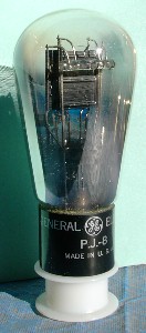 I could not find tube specifications, so had to proceed with care. The filament glowed at 1.5V, but the emission was obviously insufficient. Then, the filament was connected to a 2.5V transformer whose voltage was slowly brought up with a variable transformer, while the plate current was watched. 2.0V did not give sufficient emission, but 2.5V appeared to work well, so this was the voltage used for the heater in my experiments. The tubes were, apparently, used with filaments in series with a ballast resistor to keep the current constant with a supply (a small turbogenerator) whose output voltage varied. The filament is probably thoriated-tungsten, judging from its color when in operation, and the lack of a whitish coating to the filament.
I have found out subsequently that the filament is rated at 4.5 V, 1.1 A, so I did not do the tube any violence in the test. The maximum plate voltage is 350 V.
The large pins of the 4-pin base are always the filament or heater, and an ohmmeter proved this supposition. The two remaining pins were either PG or GP, and both alternatives were tried. The alternative that provided effective grid control was obvious, so the basing was determined (this was done at low filament voltage). Most similar triodes have this basing. The characteristics were then measured at relatively low plate voltages (less than 85V), which should give a good idea of the tube without exceeding any ratings. The service plate voltages were probably larger, perhaps as much as 300V.
The plate current was measured as a function of plate voltage for grid voltages of -1, -2, -3 and -4 V, and varied over the range of 0-3 mA. Certainly nothing here would put a strain on the tube. The plotted curves were exactly as anticipated, and the parameters were evaluated at roughly 2 mA plate current and 70 V plate voltage. The amplification factor was 8.2, transconductance 370 μS, and plate resistance 23 kΩ. The low transconductance is only to be expected from the single inverted-V filament. The tube is possibly an industrial version of the type 11, 12 or 01A triode, which had similar characteristics, but with different filament ratings (the 01A was thoriated tungsten).
 It's interesting to exercise the PJ-8 in an actual amplifier. A possible circuit is shown at the left. The cathode bias provides a plate voltage of about 50V and a plate current of about 1.5 mA. With 2.0V peak-to-peak input, the output was 11.0V, for a gain of -5.5. The predicted gain is (23k||47k)(0.37) = 5.7--good agreement. There was about 0.4V peak-to-peak of 60Hz in the output, which would not be very distracting. The tube actually is intended for a DC filament supply, but tubes of this type were often used in AC radio sets with AC on the filaments in the final amplifier. With 7.0V input, the gain dropped to -4.4 with an output of 38V. In this case the grid was drawing current, 2.7 μA on the average, so that the actual grid bias was 2.63V, 1.37V supplied by the cathode resistor and 1.26V by the grid resistor. There was no apparent distortion at any input level. In fact, the amplifier worked very well indeed. With transformer coupling giving a voltage gain of 3 at each grid, two tubes could provide a gain of about 225, a rather creditable result.
High-Frequency Triodes
Special tubes were designed to operate at frequencies above 60 MHz, where interelectrode capacitances and electron transit-time effects reduced the gain of amplifiers. Examples are the "acorn" and "doorknob" tubes for moderately high frequencies, and "lighthouse" tubes for 1 GHz and above. The electrodes were made small and the leads direct to reduce capacitance, while cathode-plate spacing was made small to reduce electron transit time.
If the signal on the grid changes significantly while the electrons are in transit, the grid finds itself accelerating and retarding electrons, which requires power in the input circuit, and is represented by a conductance that lowers the input impedance and reduces the gain by the voltage-divider effect. Transit-time and capacitance demands are somewhat conflicting, so every design is a compromise.
 The 955 is an "acorn" triode, so-called because its shape and size are much like those of that fruit. It is about 33 mm high and 13 mm in diameter, with leads projecting from its equator. The bottom of the tube has the evacuation tip. Note that the basing diagram is looking at this end of the tube. The heater takes 6.3V at 0.15A. It is a medium-mu triode that operates quite conventionally in an amplifier circuit like the one shown, which gives a gain of -19. The plate current is 2.4 mA. The advertised characteristics under these conditions are rp = 14.7k, gm = 1.7 mS and μ = 25. The maximum plate voltage is 180V, the maximum cathode current 8 mA. Full ratings apply up to 250 MHz.
We can estimate the gain as G = -1.7 (14.7k||47k) = -19, or as G = -25[47k/(47k + 14.7k)] = -19, using either the current-source or the voltage-source model of the triode. The 2.2M resistors have no significant effect. The tube was primarily used as a mixer at UHF, translating the signal down to a more manageable frequency. Of course, this circuit does not use the high-frequency capabilities of the 955, which requires special construction.
There was a series of UHF acorn tubes, the 954, 955 and 956, of which we have just discussed the 955. The 954 was a sharp-cutoff pentode, while the 956 was a remote-cutoff pentode. These three types were later repackaged as miniature tubes numbered 9001, 9002 and 9003, which were electrically identical. The 9006 was a diode for use as a detector (perveance 0.19 mA/V3/2). All four had 6.3 V heaters, and could stand voltages up to 250 V. The 9004 and 9005 were acorn diodes, the 9005 with a 3.5 V heater.
 A curious triode is the 7193/2C22 (mentioned above as similar to the 6SN7 or 6J5). It was used by the Army in World War II for some purpose, which I do not know. Bringing out both the grid and plate to caps gave the tube a mysterious appearance. It is listed among "transmitting triodes," somewhat deepening the mystery. The caps were probably to accommodate the physical shape of associated circuitry. The maximum plate voltage is 500V, and the plate dissipation is 3.5W. It is a good, ordinary, medium-mu triode. I measured μ = 18.9, rp = 5.0k, gm = 3.8 mS.
The 2C26A is a similar, but more rugged, triode with 10 W plate dissipation, and usable up to 250 MHz in small transmitters. Its μ is about 17, gm = 1.6 mS (at 5 mA plate current), and rp = 11 k&Omega (at 90 V plate voltage). Since the heater current is 1.1 A, the tube is obviously designed to use higher plate currents, and its parameters will be somewhat different in these regions. At 500 V, 10 W corresponds to 20 mA plate current. Which of the two caps is the plate and which the grid is easily determined by inspection.
Other weird triodes that I have not experimented with yet are the 6N6-G or 6B5, dual triodes with the grid of the second triode internally connected to the cathode of the first triode, the 6AE7-GT, a triode with two cathodes and two grids, but only one plate, the 6AE6-G, a triode with one cathode and one grid, but two plates, one operating on strong signals and the other on weak. These all met some special purpose, and it is remarkable that they made it into production.
The Power Triode
The output of a radio receiver was usually to a loudspeaker, which required power to drive. The low-impedance loudspeaker was coupled to the output tube by a transformer to raise the impedance presented to the plate circuit. A small receiver required something less than a watt output for adequate volume, a larger receiver perhaps 5 W. Public address systems often required more. The only tube available was the triode, so triodes were designed for this service, and were called power triodes.
 An equivalent circuit for a triode is a voltage generator μvi in series with the plate resistance rp, which drives the load impedance RL, as shown at the right. It is easy to see that the output power is given by the equation for Po, and is proportional to the square of the input voltage on the grid. Maximum power is developed when the load resistance is equal to the plate resistance, other things equal. This is an application of Jacobi's maximum-power-transfer theorem. The power is then given by the square of the input voltage times a factor called the power sensitivity, μ2/4rp.
It was necessary to reduce the plate resistance as far as possible to develop a large output current, and this generally meant a low μ. A typical early power triode was the 2A3, which had μ = 4.2 and rp = 800Ω, for a power sensitivity of 5.5 mS. A load of 2500Ω was recommended, at a plate voltage of 250V and a plate current of 60 mA, which required a grid bias of -45V. A power output of 3.5W was claimed for this class A1 amplifier, but the figures are not consistent, and the actual ouput was probably somewhat less. A voltage swing of 250V would require input swing of 79V, but this would imply a current swing of 412 mA, which is impossible. A 120 mA swing would mean input of 23V, output swing of 72V, and so a power output of only 0.25W. Unfortunately, I have no 2A3 nor the proper output transformer to see what actually happens.
Although power triodes were replaced by power pentodes and beam power tubes in the 1930's, they remained as favorites in hi-fi amplifiers. The 2A3 is now available at $76. A version with a 6.3V filament, the 6A3, and the same with an octal base, the 6B4-G, are still being manufactured, at $20 and $25, respectively. These tubes all use a directly-heated filament. Other power triodes are the types 10 ($83), 45 ($85), 50 ($273), 71A($38). These tubes typically have plate resistances around 1800Ω, transconductances around 2 mS, and amplification factors of 3 to 4. Their current high prices reflect their rarity and use in restored early tube receivers.
 Although the old power triodes have high prices, one can experiment with a newer and much cheaper tube with similar characteristics, the 12B4A ($4.60). This tube actually has planar geometry, as sketched at the right, and you can see everything. The 12.6 V heater between pins 4 and 5 is center-tapped at pin 3, so you can use 6.3 V if you want. The plate is pin 9, the grid pins 2 and 7, and the cathode pin 1. The quoted characteristics are μ = 6.5, rp = 1030Ω, gm = 6.3 mS, and plate dissipation of 5.5W. The main difference from a 2A3 is the smaller dissipation, 5.5W against 15W. However, two 12B4's in parallel should just about equal a 2A3, with rp = 515Ω, gm = 12.6 mS, and the advantage of a higher μ.
 A power amplifier using a 12B4 is shown at the left. The circuit should be quite familiar. I used the T31 output transformer that I had available, which is probably not an ideal choice. A 2.5k load would probably be better. The 500Ω cathode resistor is two 1k resistors in parallel to get a suitable power rating. The power sensitivity of the tube is 10 mS, about twice that of a 2A3. The circuit works quite well, a 12V input producing a 60V output swing, for a gain of -5.0, exactly what is expected. A 30V input swing should give an ouput swing of 150V, and a power output of 0.56W. With a 2.5k load, this would be 1.12W, a fairly good performance. The plate voltage is limited to 150V by the power dissipation (150V x 32.4 mA = 4.9W). Although the voltage gain is not great, the power gain is extremely large. Like all power triodes, it requires voltage drive from a previous stage.
For comparison, I tried a 6C4 power triode in a similar circuit. The 6C4 has a 7-pin base, with 6.3V heater on pins 3-4, plate on 1 and 5, grid on 6, cathode on 7. The maximum plate voltage is 300V, the plate dissipation 3.5W. The μ of 17 means a larger voltage gain (-7.3), so it was easier to get a plate swing of 108V, and a power output of 0.29W. The cathode bias resistor was 820Ω, giving a plate current of 9.6 mA. The 6C4 is equivalent to half of a 12AU7, a popular dual triode that is still manufactured.
The unusual 10DE7 provides a very informative look at triodes. This is one of the many tubes created for television receivers, designed to handle the vertical deflection function. It is a dual triode, but the two triodes are quite different in characteristics. One is a medium-mu (about 20) triode for a blocking oscillator synchronized by the vertical sync pulse, while the other is a low-mu (about 6) power triode to drive the deflection coil. The service is rigorous, but not as rigorous as horizontal deflection. The heater takes 10V at 0.6A, intended to be part of a series string. However, for experiments it can be supplied by a 12.6V transformer in series with a 5.6Ω, 3W dropping resistor. Take care that the specified voltage is not exceeded by more than a volt at most. I purchased my example for $1.00, an excellent value.
Measure the plate characteristics of the two units, and plot them to the same scale so that a comparison can be made. The pin connections are shown in the circuit diagram below. Pins 2 and 3 both connect to the grid of the low-mu triode (unit 2). The characteristics show very clearly the difference between a medium-mu triode and a power triode. Some of the specifications are: for unit 1, plate voltage 330V max, average cathode current 15 mA (peak 60 mA), power dissipation 1.2W, grid resistor 2.2M max. For unit 2, plate voltage 235V max, average cathode current 35 mA (peak 130 mA), power dissipation 5.5W, grid resistor 2.2M max.
 These two triodes are perfectly suited for duty as a series voltage regulator, of which a circuit is shown at the right. You may already be familiar with transistor voltage regulators of this type, and will note that the circuit is exactly the same. I used an 0A3 (VR75) as a voltage reference for consistency, but a Zener diode would work as well. The absence of grid current makes the circuit somewhat easier to analyze than the corresponding transistor circuit. This is, of course, a feedback circuit. The unit 1 triode compares the voltage at the voltage divider tap on the output applied to its grid with the reference voltage applied to its cathode. The voltage difference is amplified and applied to the grid of the unit 2 triode. If the output voltage is too high, the plate current of unit 1 rises, and the grid voltage of unit 2 falls, increasing the drop across the regulator tube. It's always good to check any feedback loop to make sure that it acts in the proper direction. It is easy to find proper resistor values in this circuit. The voltage divider can be high impedance, and the VR tube current can be selected as some reasonable value. The load resistor for unit 1 is chosen to give the required drop at reasonable plate currents for the expected range of input voltages. At 250V input, this current is 3.7 mA, while the VR tube and the voltage divider each draw about 7.1 mA, for a total of about 18 mA. Unit 2's dissipation of 5.5W corresponds to a current of 55 mA at 100V drop, so this regulator can furnish about 37 mA. I varied the input voltage over a 72V range, and the output voltage varied by only 4V. With higher gain, even better results could be obtained, but this would be satisfactory in most cases.
One benefit of such a regulator is that the output voltage can be adjusted to any desired value, not just the 75, 105 and 150V supplied by VR tubes. If the divider is placed on the voltage reference, the output voltage can be less than the reference. However, the most common used of a series regulator is to obtain higher currents than the 40 mA of the VR tubes. It is only necessary to choose a series regulator tube for the desired current. A 6F6 will give 45 mA, a 6V6 50 mA, a 6L6, 6Y6 or 807 80 mA. When using these beam power tubes, the screen is connected to the plate through a 500Ω resistor so the tube acts as a triode. Beam power tubes are chosen simply because they can handle the high currents, and are easily available.
Screen-Grid Tetrodes
A second grid was introduced into triodes at an early date, but this was usually a space-charge grid between the cathode and the control grid that controlled the plate current, not a screen grid that reduced the grid-plate capacitance to make a better RF amplifier (see below). As far as plate current is concerned, the screen grid acts like the plate of a triode, and is generally held at a fixed potential. This makes the tetrode into a current source, permitting much higher voltage amplification.
To study the classic tetrode, we must go back to the series of tubes introduced by RCA around 1930, which were manufactured under license by others in addition to RCA, who held most of the important American patents. These tubes were given two-digit identifying numbers, and used the graceful ST shouldered glass envelopes. Their bases had 4, 5, 6 and 7 pins, and grid connections were often made to caps on the tops of the envelopes. They represented a mature technology, and were excellent, widely-used tubes available for many years. Some of them, with the lower numbers, used oxide-coated filaments with low supply voltages, such as 2.5 V, 4 V, and 5 V. The higher-numbered tubes used indirectly heated cathodes with the 6.3 V supply that became standard.
A familiar example was the type 80, a full-wave (two plates) vacuum rectifier, with a 4-pin base and a filament taking 2 A at 5 V. This tube later appeared as the 5Y3 with an octal base, and developed into the somewhat more capable 5U4. The type 80 was still familiar well into the 1950's.
 A good tetrode was the type 36, whose basing is shown at the right, together with that of the type 37 triode. Pins 1 and 5 are generally used for the heater with 5-pin tubes. The grid cap has a diameter of 23/64". If you do not have a real connector, bare wire can be wound to this diameter and pushed over the grid cap, since this connection does not carry significant current. The shiny perforated cylinder looking like a screen is the screen. There is another part of it inside the plate, which is the dark cylinder that can be seen by looking up from the bottom. The supports for it project above the top of the screen, as do the supports for the control grid, which are connected to the grid cap. The capacitance from grid to plate is almost completely eliminated.
 The screen grid should be connected to a constant 90V source, while the plate voltage should be variable from near 0 to about 150 V. Plate voltage and plate current should be measured with DMM's. More details are available below in the section on pentodes. The variable grid voltage supplied by a potentiometer and the C supply should also be measured. I used grid voltages of -3 and -4 V, which keep the plate current below 5 mA. For a fixed grid bias, the plate current is measured as a function of plate voltage. The result is as shown at the left. When the plate voltage approaches the screen voltage, there is a sudden drop in the plate current. The missing plate current shows up on the screen, and the total cathode current remains practically constant. There is a minimum around 60 V, below which the plate current rises again somewhat, falling to zero only for zero plate voltage.
A large part of this plate current drop is caused by secondary emission from the plate, which seems quite efficient when the electrons impact with the energy corresponding to 60 V. As the plate voltage is lowered, the impact becomes less severe, and the number of secondary electrons decreases, so the plate current rises again. The secondary electrons fall into the screen, to which they are attracted. I searched for negative plate current with my 36, but could not find it. It is rumored to occur with certain tubes, and is a definite proof of secondary emission. There is a region of negative resistance for plate voltages between 15 and 60 V, and this could be used for an oscillator. While messing around in this area, one should take care that the total cathode current is not excessive, since the screen dissipation is quite limited. A few mA seems quite safe, however.
When this tube is used, the plate voltage must not be allowed to fall below the screen voltage, or serious distortion will result (the plate resistance varies widely, even becoming negative). The usual plate voltage is about 250 V (specified as the maximum value), so the range 90-250 V is quite ample.
 Although the type 36 was the typical example in textbooks, and was a good one, there is a modern tetrode that also exhibits typical tetrode behavior, the 6CY5. This 7-pin miniature tube is listed as a "pentode" in the RCA data book, but the basing diagram shows a tetrode, and, of course, it acts like one. It was used as an rf amplifier in TV receivers. It is available at a lower price than the type 36. The maximum plate and screen voltages are 150V, the maximum cathode current is 18 mA, and the plate dissipation is 1.7W. The heater takes 0.2A at 6.3V. The capacitance between grid and plate is only 0.03 μF. The input capacitance is 4.5 pF, the output capacitance 3.0 pF. The transconductance is high, advertised as 8 mS, but the plate resistance is low for a tetrode, 100k.
I put 80V on the screen, and ran plate characteristics at Vg1 = -1.0 and -2.0 V, for plate voltages up to 120V. The curves showed nice tetrode dips when the plate voltage was below the screen voltage. I found gm = 7.1 mS at 100V. At Vg1 = -1.0V, rp was only 30k at 100V on the plate. For Vg1 = -2.0, rp had increased to 107k. The amplification factor in the latter case was 760 (of course, this means little for screen-grid tubes). For plate voltages above the screen voltage, 86% of the cathode current went to the plate, 14% to the screen, and this division,a bout 6:1, did not change for different Vg1.
Space-Charge Grid Tetrodes
Towards the end of the vacuum-tube era, tubes were developed that could work entirely off the 12V of an automobile battery, without the need of a troublesome vibrator supply (see below for an extended discussion). The key was the reintroduction of an old technology, the space-charge grid, invented by Schottky around 1919 as an alternative to the use of "soft" or gassy tubes. With only 12V on the plate, it would be impossible to produce any reasonable plate current. For any practical power, the plate current would have to be large, but this would be impossible in a space-charge controlled tube. A grid located in the space-charge region with a positive potential would counteract the space charge and allow a large plate current to flow. In Schottky's day, this was exactly the same problem confronting him. The control grid in such a tube is outside the space-charge grid, and controls the plate current in the usual way.
An example of such a tube is the 12DL8, in a 9-pin miniature envelope. This tube contains a full-wave diode and a space-charge tetrode, meant to operate off a 12V battery. The 12K5 is identical, except without diodes, and comes in a 7-pin package. These tubes offers the chance to experiment with vacuum tubes without the usual large voltages. The maximum plate voltage is 30V, the maximum grid-1 (space charge) voltage is 16V, the minimum grid-2 (control) voltage is -20V. The maximum current for each anode in the full-wave rectifier is 5 mA. This rectifier is intended for signal rectification (detection), not power. The diode cathode is pin 8, and the anodes are pins 1 and 9. The tetrode plate is pin 6, cathode pin 2, grid-1 pin 3, and grid-2 pin 7. The heater, which can stand anything from 10 to 15.9 V at 0.4 A, AC or DC, is pins 4 and 5. The heater is satisfactorily supplied by 12.6 VAC.
Characteristics can be run the usual way. There are three voltages to control, and two currents to be measured. Grid-2 is always negative, and carries no current. Grid-1 is always positive, and carries a considerable current, normally larger than the plate current. Set the grid-1 voltage at some convenient value, say 12V, and measure IP as a function of VP for reasonable values of VG2, say 0, -1, -2, -3 and -4V. Vary the grid-1 voltage and observe that it is the principal control of the plate current; when it is zero, there is only a very small plate current.
The plate characteristics are of an unfamiliar appearance mainly due to the expanded plate voltage scale. They are quite curved, so the dynamic parameters vary considerably. I found that gm = 15 mS and μ = 6.6 in the neighborhood of 20 mA plate current and 12 V plate voltage, giving a small plate resistance of 440Ω. This tube is specifically designed to be a power amplifier, so these parameters are reasonable. The tube specifications quote a power output of 40 mW. The large transconductance is to be noted. The tube itself is not small, to give as large a cathode area as possible.
 A voltage amplifier that can be constructed and tested is shown at the right. It must be understood that this tube is not suited to this role, and would more likely have an output transformer driving a loudspeaker. The low value of the cathode resistor is necessary because the cathode current includes both the plate current and the space-charge grid current, which here is about 90 mA. With a 2V peak-to-peak input, the output is 6.5V, for a gain of -3.25. This is just what is expected from the measured characteristics. The bias current varies with the input voltage (decreasing as the input amplitude increases), and in this case is about 17 mA. The space-charge grid current is 74 mA. These are rather large currents, but the low voltages mean that only modest power is involved. Note that the input impedance is high, set by the 1M grid resistor, and the output resistance is low.
The modern space-charge grid tetrodes allow us to work with a tube type from the dim past of vacuum tubes. Most texts never mention this kind of tube.
Contact Potential Effects
This is a good place to mention contact potentials, since you will probably run into their effects when experimenting with low-voltage tubes. Because of contact potentials, the voltages you measure with a DMM are not the actual voltages between electrodes, as seen by the free electrons, but differ by up to a few volts from the true potential differences.
 To understand this, let's review electrons in metals. One or more of the outer electrons of each metal atom is free to wander in the field of the ion cores, effectively binding the metal together. The positive ions create a potential well, as shown in the figure, and the electrons occupy the states of lowest energy. Note that electron energy increases upwards; since electrons are negatively charged, this means that voltage gets more negative upwards. There are not many more states than electrons, so they fill up the states up to some energy called the Fermi energy at 0 K. At ordinary temperatures, there is little difference, since the thermal energy is small compared to the kinetic energy of the electrons near the Fermi level.
If an electron is given enough energy, by thermal agitation or absorption of light, it may be separated completely from the metal and wander freely. The amount of energy necessary to just get outside is called the work function. Anything more goes into kinetic energy of the electron. The free electron can now be accelerated or decelerated by electric fields outside the metal in space. Work functions measured by thermionic, photoelectric and contact potential measurements agree roughly, but they depend sensitively on the surface preparation.
What happens in a vacuum tube is illustrated in the figure below. Suppose metal 1 is the cathode and metal 2 is the anode or grid, and the connections are made by a third metal 0 (there could be several such metals, but they all will act like metal 0). At the left, metals 1 and 2 are connected by a wire of metal 0. If metal 0 includes a DMM, it would show 0 V and, of course, no current would flow. However, the Fermi levels of all three metals must line up for equilibrium, making a level surface on which the electrons will not tend to roll one way or the other. It is clear that in this state of equilibrium, the surfaces of metals 1 and 2 will not be at the same electrostatic potential. An oxide-coated cathode has a work function of about 1.0 V, while a nickel plate or grid has a work function of about 5.0 V. When the Fermi levels align, the cathode is 4.0 V positive with respect to the other electrode.
At the right, we have connected a source of emf Eb into conductor 0. A source of emf maintains a difference in the Fermi levels equal to its voltage. With the polarity shown, the cathode 1 has now become negative with respect to the anode 2, by an amount equal to the applied voltage less the difference in work functions. If the device is a thermionic diode, current can now flow from cathode to anode. The actual plate voltage is about 4 V less than the meter says, because of the contact potential. In practice, things are a bit more complicated, because of space-charge effects. When you measure the V-I characteristic of a diode, there appears to be a small positive plate voltage when the measured voltage is zero, and a little current flows. The reason is that the electrons are emitted with some kinetic energy, and a negative space charge is created around the cathode. The actual emission to the anode comes from the minimum of this potential well, which is several volts negative, and so the plate may be slightly more positive than this minimum, in spite of contact potentials.
Pentodes
Pentodes were introduced to eliminate the restriction on plate voltage swing of the tetrode, by getting rid of the dip. A new third grid between the screen grid and the plate, the suppressor, was held at cathode potential and repelled secondary electrons back into the plate, as well as making the electron division independent of plate voltage. This made pentodes useful for audio and power amplifiers in general as well as for RF amplifiers. The screen grid, at signal ground, reduced the grid-plate or Miller capacitance to very low values, less than 1 pF, as for tetrodes. The consequent reduction in negative feedback at high frequencies made RF amplification possible without hard-to-adjust neutralizing circuits. Therefore, pentodes were always found as RF and IF amplifiers in radio receivers. These were voltage amplifiers, and of two kinds: sharp cutoff and remote cutoff. The remote cutoff pentode had a control grid of uneven spacing, so that when the bias was large, the transconductance of the tube became small, limiting the gain so that the amplifier would not be overdriven and produce distortion. Typical RF pentodes are the octal 6SJ7 (sharp) and 6SK7 (remote), or the miniature 6AU6 (sharp) and 6BA6 (remote). Usual plate currents were 10 mA or less.
It was also found that pentodes, like tetrodes, made excellent voltage amplifiers, because of the increased plate resistance. A pentode acted like a current source instead of a voltage source. This put a premium on high transconductance, which made large gain possible in a single stage. Gains of 40 or 50 are quite practical in a pentode voltage amplifier, in contrast with gains of around 15 for a medium-mu triode amplifier. On the other hand, the gain of a stage now depended sensitively on the load resistance; if this varied with frequency, as for a loudspeaker, so did the gain. This was only a disadvantage in final power amplifiers, of course. Sharp-cutoff pentodes were widely used as audio amplifiers.
 The circuit for measuring pentode characteristics is shown at the left. The tube used as the example is the 6SJ7, but any sharp-cutoff pentode will do, such as the miniature 6AU6. It makes things very easy if you have four DMM's for the various measurements. The screen supply can be fixed-voltage. I used 105 V from a VR tube at first, later the all-in-one supply described above, which proved very convenient. The plate supply should be variable, as well as the grid bias. When screen and plate voltages are first applied, the grid bias should be set to some negative value to avoid surprise. The cutoff bias can be estimated at about 1.5 times the screen voltage divided by the screen amplification factor (take as 10 if you do not know it beforehand). Vacuum tubes are much more rugged than transistors, and a momentary oversight will not usually result in disaster. The suppressor grid of a pentode is always connected to the cathode, and is often not even brought outside the envelope, but is connected internally to the cathode.
The first thing to do is probably to measure the screen or triode-connection characteristics. To do this, connect the screen and plate together and measure the total current with a single DMM. Set the grid bias, and then measure the total current as a function of voltage over the range available to you. Repeat for several values of the grid bias, so you obtain a family of curves like the plate characteristics of a triode. From these curves, estimate the amplification factor, plate resistance and transconductance, just as for a triode. Now connect the plate and screen to their separate supplies, and run plate characteristics for a fixed screen voltage. In this case, the cathode current will be about constant, and will divide between the screen and plate. Determine the ratio of division at various plate voltages.
For the 6SJ7, I found gm = 2.56 mS, which is quite high for this tube. With 75 V on the screen, cutoff was at about -5 V on G1, and the screen resistance rg2 was about 8200Ω. I also found that the screen current is about 0.3 of the plate current, roughly independently of voltage, if the plate and screen are at about the same voltage. The screen takes a rather large proportion of the cathode current in such tubes, but this is not deleterious since the total current is small.
The suppressor grid of the 6SJ7 is brought out to a separate pin, and is normally connected to the cathode at the socket. By testing the tube with the suppressor grid connected to the plate, you can see that the suppressor grid is a bit more complicated in action than usually thought. It makes little difference whether the grid is connected to plate or screen, showing that the current intercepted by it is small, and does not affect the results. When the plate voltage is higher than the screen voltage, nearly all the current goes to the plate. As the plate voltage is decreased below the screen voltage, the screen current rapidly rises until it is about equal to the plate current. This rapid variation in the plate current would be quite annoying. The suppressor grid, when connected to the cathode, does indeed send secondary electrons back to the plate, but it is evident that it also affects the distribution of the cathode current between plate and screen, and the effect of secondary electrons is not as great as it may seem. With the suppressor grid connected to the cathode, as is the usual case, the plate and screen currents are both practically constant, with the screen taking about 20%. One could use the suppressor grid to change the plate current, and, in fact, this is done in the pentagrid converter, which has a different structure and a special grid for this purpose, as we shall see below.
 A pentode voltage amplifier using a 6SJ7 is shown at the left. The AC gain of this amplifier is close to gm = 1.6 mS times 68.8k, or -110. It won't be quite this high with a 90V B+, but will still give a lot more gain than the triode amplifier. My 6SJ7 gave a gain of -60 at Vbb = 90 V, and Vp was 27.2 V, showing that the plate current, 0.63 mA, should be reduced a little to raise the plate to about 45 V. The 6SJ7 tested was very close to specifications, despite its age.
A good example of the remote-cutoff pentode is the type 39/44, which uses a 5-pin base and a grid cap, so it is interesting to experiment with. You could also use a type 78 with a six-pin socket and grid cap, or the identical 6K7 with an octal base, or the later 6SK7. All these tubes should give equivalent results. They were very popular for rf and if amplifiers. Their feature, as we have mentioned, is that the transconductance, and so the gain, could be varied by changing the grid bias. The 39/44 has a maximum plate voltage of 250V, and a maximum screen voltage of 90V. The heater is pins 1-5, taking 0.3A at 6.3V. The plate is pin 2, the screen pin 3, the cathode pin 4, and the control grid is connected to the cap on top. In lieu of a proper grid connector, I use a short piece of 3/8" I.D. lucite rod to fasten the grid connection.
 If you run characteristics of the 39/44, using 90V on the screen, the transfer characteristic looks like the figure at the right. Above about 4 mA plate current, the transconductance is about 1.0 mS, and below about 2 mA plate current, it is about 0.2 mS. It varies smoothly, of course, so the characteristic is curved. This means that there will be distortion for large grid swings, but the tube is not used in this way, like a power pentode would be. I actually found rather linear variation for small and large plate currents. The plate resistance is about 1 MΩ, so the tube is a pretty good current source. In a transistor amplifier, we can change the gain by changing the collector current, since the transconductance is proportional to it.
 The circuit at the left is closer to the way the tube was used in practice, when the load was usually a tuned IF transformer. In place of the transformer, there is a 10 mH rf choke. The results of the experiment may depend somewhat on what choke is used; this one is a Digi-Key M7103, with a ferrite or powdered iron core. Vary the frequency of the signal source to find the point of maximum gain; in my case, it was at 269 kHz. You will probably be astonished by the gain--I found -318! The phase shift is 180° at maximum gain, so the tube is working into a load of about 320k. Obviously, the 10 mH coil is in parallel resonance at this frequency. If you compare output and input with the scope, the output will lag at a lower frequency, and lead at a higher frequency, as expected, and the resonance has a fairly high Q. The actual coil is more or less equivalent to a 35 pF capacitance in parallel with the 10 mH. Above 269 kHz, it is a capacitor, not an inductor!
In a typical Circuits or Electronics course, the 10 mH choke would be just that, and would have an inductive reactance of about 63k at 1 MHz. Woe to the student who would say that it would have a capacitive reactance of 4500 ohms at this frequency, but it would have, all the same! Above 270 kHz, this choke is more like a short circuit than a choke.
If you replace the 10 mH choke by a resistive load, you can see how the circuit would be affected. Now there is a voltage drop in the load resistor, so it is limited to about 33k if the plate current is 4.8 mA (obtained by a 510Ω cathode resistor), and the gain to about -33. If you try to overcome this by using a small plate current, say 1.6 mA (cathode resistor 4700Ω), then a larger resistor, say 47k, could be used. However, the gain would now be only -9.4, since the transconductance is so much lower. A remote-cutoff pentode is not suitable for low-plate-current voltage amplifiers--a sharp-cutoff pentode should be used instead, or even a high-mu triode. However, the remote-cutoff pentode is just the thing for reactive or transformer-coupled loads, since these do not reduce the plate voltage. It is very satisfying to be able to compare the behavior and use of remote-cutoff, sharp-cutoff and power pentodes.
 An RF amplifier using a 6SK7 remote-cutoff pentode is shown at the left. You could also use the miniature 6BD6, which is a little less expensive, or the 6-pin base type 78, the prototype for these tubes. The 6SK7-GT is very well shielded, with a Cgp = 0.005 pF, which makes the Miller effect negligible. Note that the grid bias can be varied. The purpose of this is to show the variable gain of the amplifier. In a radio receiver, the grid bias is supplied by the AVC (automatic volume control) circuit, and is the dc value of the rectified signal at the detector (see below). The gain of this amplifier is near -100 for zero bias, decreasing to -8 at a bias of -12V. Adjust the frequency of the signal generator for maximum output. Since this circuit has only one tuned circuit, there is no problem with alignment. Measure the gain of the circuit as a function of grid bias. The decrease of gain is practically linear up to about -8 V, but then begins to curve over rather than decreasing abruptly to zero. If we assume an ideal linear dependence, then the output signal is limited at the value that gives the cutoff bias. In a practical case, the amplitude of the output varies slowly with the amplitude of the input. If the input signal is weak, we get the full gain of the amplifier. Note that the only components in this circuit, besides the tube, are the two air core transformers. A practical circuit would have some other components, but this circuit shows the principle at its simplest.
 The sharp-cutoff pentode made the best high-gain audio voltage amplifiers. A circuit with gains of over 100 is shown at the right. The tube is the type 77, which uses a 6-pin base. The heater is connected to pins 1 and 6, taking 0.3A at 6.3V. I used the 77 for the fun of it, since it is not an expensive tube, the construction is evident, and it harks back to the 1930's. The outer electrode that you see is the external part of the screen grid, not the plate. Peek under it to see the actual plate. The octal 6J7 has the same electrical characteristics (except that the 77's screen voltage is 100V max.). The 6SJ7, which we looked at above, is also very similar. The "S" meant single-ended, since the 6SJ7 does not have a grid cap. Two sets of values for the components are shown for this amplifier. The upper values give a gain of -164, a plate current of 135 μA, a plate voltage of 29V, a screen voltage of 17V, and a grid bias of -0.8V. The lower values give a gain of -117, a plate current of 262 μA, a screen voltage of 20V, and a grid bias of -0.9V. It is necessary to have a low plate current to permit a large plate resistor for high gain, so the screen voltages are quite low. No load is shown for the amplifier, but it would usually be a high-impedance grid.
Note that an attenuator is shown at the input. This makes adjusting the signal generator much easier. I noticed a little 60Hz hum on the output, which is not surprising in view of the large gain, and the length of unshielded wire going to the grid cap. When fed a square wave, the amplifier showed a rise time of around 25 μs, and a sag of 1.0V in 4.4 ms when the amplitude was 13.4V peak to peak. These figures agree pretty well with a measurement of the bandwidth by varying the input frequency, which gave 35 Hz to 17 kHz.
In this circuit, we use the screen to hold down the plate current so a large plate resistor can be used even with a modest supply voltage, while keeping the plate voltage high enough to allow a reasonable output swing. Even with the reduced transconductance, we can achieve good gains, considerably higher than those possible from a triode.
Power Pentodes and the Beam Power Tube
To deliver power, large plate currents are required. The pentode offered the possibility of large plate currents controllable by a grid that was held negative, so it would draw no power and could be driven by a voltage amplifier, in contrast with the power triode. For this reason, power pentodes were developed and became very popular. These tubes, such as the 6F6, controlled a large output power with a small voltage input, much less than would be required for a triode with the same output. Plate currents ranged upwards to 80 mA. However, the large current intercepted by the screen grid, up to 20 or 30% of the total, was a limiting factor.
 A modification of the pentode, the beam power tube, solved this problem. Beam-forming electrodes, as shown in the sketch on the right, connected to the cathode shaped the electron stream into a dense beam on either side of the cathode. The control-grid wires, at a negative potential, repelled the electron stream creating a shadow, in which the screen grid was located. This greatly reduced the screen current, and increased the permissible plate current. The space charge of the electron beam served to drive secondary electrons back to the plate without the necessity of a suppressor grid, although in some cases the suppressor may be retained. Such tubes could be made with quite high capacity, and became popular even for transmitting tubes handling kilowatts of power.
Among receiving tubes with 6.3 V heaters, the RCA tube manual lists 10 power pentodes, with plate dissipations up to 11 W (for the 6F6), but 25 beam power tubes, with plate dissipations up to 24 W. Television required rugged tubes for vertical and horizontal amplifiers (to drive the deflecting coils), and many of these were beam power tubes. Nearly all small broadcast receivers used a beam power tube as the final power amplifier to drive the loudspeaker. The 6AQ5, the 6V6, the 7C5 and the larger 6L6 are good examples.
There are also small power pentodes classified as transmitting tubes, such as the miniature 6AK6, which is like the octal 6G6-G receiving power pentode, and the 5763, with 12W plate dissipation. These tubes always have the suppressor grid brought out to a separate pin, to permit suppressor-grid modulation. Although screen-grid modulation of a pentode is not very successful, suppressor-grid modulation is quite advantageous, since no driving power is required, only voltage. This alternative is not available with triodes. At the other end of the scale, beam power tubes such as the 4-250A dissipate 250W, and give power outputs near a kilowatt. At low plate currents, beam power tubes show the tetrode dip, while pentodes do not.
For the triode-connected 6AQ5, I found μ = 10, rp = 2.38 k and gm = 4.2 mS, all typical of a power tube. The 6AQ5 was used as a triode in television vertical deflection amplifiers, a very demanding service where the instantaneous plate voltage could rise to 1000 V, and the grid voltage sink to -250 V, because of inductive effects in the deflection coils. Conditions like this made it difficult to replace vacuum tubes with transistors in television receivers. Any pentode can be used as a triode by connecting the plate and screen together, and many were typically so used.
I ran curves for grid voltages of -2, -4, -6, -8 and -10 V. The plate resistance at a plate current of about 30 mA was 44k, and it increased slightly at lower plate currents. The transconductance was about 2 mS at plate currents below 10 mA, increasing to about 4 mS at higher currents. As the plate voltage was decreased, the screen current increased, the total current remaining about constant. The screen current was about 10% of the total, a rather low value typical of beam power tubes, where the beam is directed into the gaps between the screen grid wires. At even lower plate voltages (below 50 V) the plate current would drop rapidly, the electrons preferring the positive screen. If you enter this region, be careful of excessive screen current. The screen is limited to 2 W dissipation, while the plate can dissipate 12 W. Plate currents can go up to 200 mA with positive grid bias; the limitation is on power dissipation, not raw current. Cathodes can usually supply any amount of current you want, but power dissipation governs the limits of the tube. Grids, in general, can dissipate rather little power. In our experiments, the control grids should not be given a fixed bias above 0 V with respect to the cathode.
 A pentode power amplifier is shown at the left. The 6K6 is an octal power pentode (the 7B5 is the loktal equivalent), a very satisfactory tube with a plate dissipation of 8.5 W and a screen dissipation of 2.8 W, maximum plate voltage 315 V, maximum screen voltage 285 V. It is not a beam power tube like the 6AQ5, but is a straight pentode, giving relatively low distortion. The tube is operated well within its limits in this circuit, with a rather low plate voltage of 105 V. Nevertheless, transformer coupling means that the output swing can be as large as 150 V, giving an output of over 2 W into the speaker. The transformer has a turns ratio of 25:1 to match 8Ω to 5k in the plate circuit. It weighs 0.7 lb, and is not tiny. The transformer must work into a low impedance to be efficient. It reflected a 45Ω speaker as 15k in the plate, instead of the expected 28k. It is designed to handle the DC bias current of a class A amplifier, here a little over 9 mA. The speaker was a good-quality 8 Ω speaker rated at 45 W, and the amplifier drove it quite capably.
If you plot the plate characteristics of the 6K6 for a screen voltage of 105, the quiescent point can be plotted, and a load line for 5k through it. Using the oscilloscope, find the maximum and minimum plate voltages for a certain input voltage. The average output power is the square of the voltage swing divided by 8 times the load resistance (the factor of 8 converts peak-to-peak to rms). The actual load line was closer to 6k, and the gain was -10. From the plate characteristics, a transconductance of 1.8 mS was measured at 9 mA plate current, so everything hangs together quite well. This circuit is nowhere near the maximum capability of the 6K6, but works very well. It should be driven by a voltage source of about 7 V amplitude for maximum output, which sounds quite loud.
 A power amplifier using a beam-power tube is shown at the right. The 7C5 is the loktal equivalent of the 6V6 or 6AQ5, to which it is electrically very similar. The screen is supplied through a series resistor from the plate supply, with a bypass capacitor, a typical arrangement. 470k is the maximum recommended grid-circuit resistance. At quiescence, the plate voltage was 248 V, the screen voltage 227 V, and the cathode voltage 13.35 V. The gain was -16 at 600 Hz, but increased with frequency to about -28 at 2 kHz, a result of the changing impedance of the loudspeaker. This difficulty is completely solved by the use of negative feedback to set the gain. This amplifier produced an output of about 1 W for a 12 V peak-to-peak input, enough to produce a very loud sound.
At low plate and screen voltages, a remarkable oscillation is observed. This was seen at about 70 V supply voltage, much less than would normally be used. The oscillation at about 250 Hz was quite strong, with sharp dips of plate voltage. The oscillation did not involve the grid at all. In fact, the amplifier amplified normally when a signal was applied to the grid, the output superimposed on the oscillation. This seems to be a dynatron oscillation caused by a negative-resistance segment of the plate characteristic of a tetrode, called the dynatron region. When characteristic curves were run, a negative-resistance region was quite evident at a screen voltage of 102 with -5V on the control grid. Apparently, at these low plate currents the suppressor effect of the beam is insufficient to overcome secondary emission.
In the low-voltage region where the characteristics were measured, I found rp = 85k and gm = 2.95 mS, reasonable values. All beam power tubes like this are rather expensive, especially the 6V6 and 6L6, but the 7C5 is a very good alternative and modest in price.
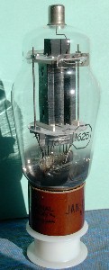 A famous beam power tube was the type 807, a graceful large tube with an ST envelope and a plate cap, shown in the photograph at the right. It appeared with a 12.6V heater as the type 1625, known in military service as the VT-136 and used in many military radio sets as an RF power amplifier. These days, it is considerably cheaper than the 807. With 30W plate dissipation, the 807 or 1625 could deliver well over 100W RF power when used in push-pull, operating at full ratings up to 60 MHz. These tubes also could handle heavy-duty audio amplification. The basing of the 1625 is shown below on the left. For some reason, it used a rare 7-pin base instead of the standard 5-pin base of the 807. The internal construction can be glimpsed at the bottom of the plate, and the beam-forming electrodes, as well as the aligned grid wires, can be seen. It is noted in specifications that the plate did not glow when the tube was used within its amateur (ICAS) or commercial (CCS) ratings. If a plate gets hotter than when it was outgassed at the evacuation of the tube, it may emit gases and ruin the tube.
 The maximum plate voltage is 750V (the maximum when oxide cathodes are used), the maximum screen voltage 300V, and the screen can dissipate 3.5W. In normal service, the control grid is taken positive as well as negative, and, of course, draws power. Nevertheless, much less drive is required than a triode would demand. With 0V on the control grid, and a screen voltage of 250V, the plate current is about 200 mA. When used as a class C RF amplifier, the grid bias would be around -50V, holding the tube beyond cutoff in the absence of a signal. I made measurements at low voltages and currents, from which an idea of the tube's operation can be formed. With 100V on screen and plate, I found a transconductance of 2.8 mS and a plate resistance of 39k. As a triode, the amplification factor is 8, the plate resistance 2900Ω, and the transconductance about 3 mS (not all at the same point). The tetrode dip occurs only below 50 mA plate current, and was obvious in my measurements. Incidentally, I found a large copper-plated spring clamp to make the plate contact, lacking a proper plate cap.
Battery Tubes
In the early days, nearly all radios (and other electronic apparatus) were powered by batteries, usually primary cells. With the rise of central power distribution, apparatus could be powered (and storage batteries charged) from the AC line, which was a practically unlimited, cheap source so far as radios were concerned. Transformers made high-voltage power supplies easy to build. Low-voltage filaments were largely replaced by 6.3V heaters and unipotential cathodes since power was now cheap. However, there still remained a demand for portable radios beyond the reach of power lines, and these were necessarily powered from batteries. The emphasis here had to be on small power drain, since battery power is expensive. Typical batteries were 1.5V and 3.0 V for filaments ("A" batteries), and 45V or 90V for plate supplies ("B" batteries), both the usual Leclanche "dry" cells. Filaments were generally used, because of their much greater efficiency in mA per watt. Typical battery tubes had filaments taking only 50 mA at 1.4V, only 70 mW. Plate currents were not high, since a few mA would be quite sufficient. For experiments with battery tubes, a D cell in a holder is an adequate filament supply, good for about 100 hours of service. Even an AA cell will do for experiments.
 The 1LH4 is a loktal battery triode, which is shown in a voltage amplifier at the left. A similar octal tube is the 1H5-GT, and either will do in this experiment (but the basing is different!). A diode plate is included, connected to pin 4, and using the negative side of the filament as its cathode. The diode is not used in this circuit. The maximum plate voltage is 110V, but this can be exceeded a little in testing. I measured the characteristics for plate voltages of 125V and less, at grid voltages of 0.0, -0.5 and -1.0V (relative to the negative end of the filament). The plate current was always less than 1 mA. My results were μ = 62, gm = 340 μS, and rp = 182kΩ. These values are close to the published values. The characteristics are noticeably curved in this region, so the parameters will vary with plate current. The apparently low value of transconductance is quite reasonable for the small plate currents at which the tube is used.
The amplifier shown gave a voltage gain of G - -40, with an input of 0.4V peak-to-peak. The plate current was about 100 μA, which made the plate voltage 77V and the grid bias -0.26V. The bandwidth of the amplifier was quite good, roughly from 10Hz to 50kHz. It should be noted that the total power drain of this circuit is no more than 83 mW, of which most is the filament power. This is very economical for a normal-sized tube. The tube remains quite cool in service, incidentally.
 A pentode voltage amplifier with a gain of about -33 is shown at the right, using a 1U5, a sharp-cutoff pentode which comes in a 7-pin miniature package. Note the polarity of the filament supply, which is important, since it supplies a little grid bias as well. Since the voltages and currents are low, you can use the same 1/4W resistors used with transistors. The capacitors must have an appropriate voltage rating, of course. The 10M resistor is a "grid leak" that will prevent the grid from going positive. It charges on the positive excursions of the grid to provide whatever bias is necessary. The plate current was 61 μA, and the screen grid current was 20 μA. The screen grid potential is above the plate's in this circuit. Pentodes offer the capacity for controlling the plate current through the screen voltage, so that the plate voltage can be what is required. For higher voltages, the screen grid is normally at the same or lower potential as the plate, on the average. The grid voltage cannot be measured accurately with a DMM or scope, since the bias conditions will be disturbed. However, you will find that the amplifier works very well. Measure the gain the usual way, with a function generator and oscilloscope.
Radios for motor cars had 6 V DC available, which was right for 6.3 V heaters, but could not be used for the B supply--even now, 6 V is inconveniently low for transistors. The usual solution was a vibrator supply. Contacts on the magnetically-driven vibrator armature converted 6 V DC to alternating current, which was stepped up by a transformer and then rectified to DC again (sometimes by contacts on the vibrator) for the B supply. Vibrators were electrically very noisy, and had short lives, but were widely used until solid-state equivalents became available. They came in cylindrical metal cans, and looked like electrolytic capacitors. The 0Z4, mentioned elsewhere, was a rectifer specifically for vibrator supplies. Another possibility was the dynamotor, a motor-generator with a single rotating armature and brushes, which could supply more power than a vibrator and was more reliable. However, they were too expensive for general commercial use, though widely used in the military.
When 12 V became the automotive standard, vibrator supplies or their solid-state equivalents, could still be used. Tubes with 12.6 V heaters were already common. Many had the heater center-tapped, so they could be used equally well on 6.3 V. However, 12 V is high enough to be used directly as the plate supply if the tubes are specially designed. A range of tubes was produced that could be used on 12 V only, without any high voltage at all. We have already discussed the 12DL8 and 12K5 space-charge-grid tetrodes, and how the space-charge grid allows larger plate currents for small plate voltages. There were approximately 15 tube types designed for 12V use, of which only three, the 12DL8, 12DS7 and 12K5 are space-charge grid tetrodes, behaving like triodes. The other tubes are of conventional construction, in general having low plate currents, less than 1 mA in many cases. These include twin-diode triodes (12AE6, 12FK6, 12AJ6), sharp cutoff pentodes (12AF6, 12BL6, 12CX6, 12EK6), remote cutoff pentodes (12CN5, 12DZ6), twin-diode remote cutoff pentode (12F8), pentagrid converter (12AD6), pentagrid (variable gain) amplifier 12EG6, and a twin-diode power screen-grid tetrode, 12J8. The last tube can deliver 20 mW output power, half of what the 12DL8 can do.
 The 12EK6 (also known as 12DZ6 and 12EA6) is a screen-grid pentode for low-voltage use. A voltage amplifier using this tube is shown at the left. This tube was generally used as an IF or RF amplifier, so the load would have been a resonant circuit, not a resistor, giving much higher gain. However, the resistive load is easy to experiment with. There is no voltage to waste for cathode bias, so grid-leak bias is used. When a signal is applied, the bias will adjust itself so that the top of the input waveform is clamped to 0 V. Vary the input amplitude to verify this. This circuit works with an input of up to about 2 V peak-to-peak, perhaps best for an input of around 1.0 V p-p. The output voltage is then about 5.8 V p-p, the plate potential is 6.0 V, plate current 1.8 mA, and gain about -5.5, corresponding to a transconductance of 1.8 mS, about right from measurements of the characteristics and the position of the operating point in this case. The transfer characteristic is rather curved, leading to considerable distortion for larger amplitudes. Nevertheless, it is remarkable that the circuit works so well at such a low voltage.
As a triode (plate, suppressor and screen connected together), the 12EK6 has μ = 8.5, gm = 6.3 mS and rp = 1.35 kΩ. The transconductance varies considerably with plate current, which gives rise to distortion for large signal amplitudes.
These tubes make vacuum-tube experiments very easy without requiring high-voltage supplies, only what is found in a normal transistor lab.
Sub-Miniature Tubes
The smallest regular electron tubes were the subminiature tubes, designed for battery-powered portable apparatus, from hearing aids to radiosonde transmitters. Typically, the lead wires were brought out through the press seal without a base, but there was also a subminiature base used for a few tubes. As an example, you can work with the 1V6, a pentode-triode with a filament taking 40 mA at 1.25V (the filament supply can be a D cell). The tube is 40mm x 10mm x 7mm, approximately. The maximum plate voltage is 45V, and typical plate currents are less than 1 mA.
 A sketch of the 1V6 and its connections is shown at the right. On the press seal, there is a red dot that identifies what I have called pin 1. The filament is located at the center of the tube, with the pentode on one side and the triode on the other. The triode shows a μ of about 10, rp = 18.6 kΩ, and gm = 440 μS. The pentode has gm as high as 694 μS above 500 μA plate current, but it drops considerably at lower plate currents. The two devices can be tested as usual, taking care not to exceed 45V or 1 mA. Note that the pentode and the triode share the same filamentary cathode.
 Unfortunately, I do not have any actual circuits that used a 1V6, but the amplifier shown at the left may be studied. It gave a gain of -14 with a plate current of 357 μA, so the effective transconductance was 298 μS. I substituted a 100k plate resistor, but the gain only increased marginally, to about -17. By experimenting, you may be able to get more gain from the tube. At low plate currents, the amplifier oscillated in an odd manner, and there were other peculiarities seen while fiddling around, but I did not take the time to track them down.
117-Volt Heater Tubes
A few tubes were made with 117V heaters that could be connected directly across the AC line. This might seem a good idea, but hum difficulties (from unavoidable leakage between heater and cathode as well as ordinary pickup) rule out such heaters for tubes handling low-level signals. However, there is no objection in rectifier diodes, or in the final power amplifier of a radio set. All of these tubes contain half-wave rectifier diodes, meant to supply power to the complete set. The 117Z3 and 117Z4 are simply diodes, while the 117Z6 is a dual diode with separate cathodes, intended as a voltage doubler. The rest of the 117V tubes include a power pentode that can give a signal output of up to about 1W. The pentode uses most of the current rectified by the diode, which has a peak inverse rating of 350V and an average DC current of 75 mA. These tubes are the 117L7, 117M7, 117N7 and 117P7, all roughly similar, though the 117N7 seems the most capable. They all come in GT envelopes, so you can see inside. The heaters for the other tubes in the set were connected in series across the line, with a dropping resistor if necessary. There is a 70L7 rectifier-pentode that does not use up all the 117V.
I tested a 117N7, but any of the others will perform equivalently. Connect pin 7 to the hot side (black) of the AC line, pin 2 to the grounded side (white) of the 120V line. When the power is first turned on, there will be a disconcerting white flash near the base of the tube. Do not panic--this is normal. The inrush surge heats the short length of heater between the cathode and the connection to incandescence while the rest of the heater is heating up and its resistance is increasing. Pin 7 is also the anode of the rectifier, and pin 8 is its cathode. The transconductance of the tube can be tested by connecting about 100V to the screen (pin 5) and plate (pin 3) and varying the grid (pin 4) potential. The cathode, pin 6, is connected to common. I varied the grid voltage from -2.4V to -8.1V, the range encountered in operation, and found that the transconductance was quite close to 7.0 mS, exactly in line with the tube data. The plate current was in the range 45.6 - 78.3 mA, which is quite high but necessary for the desired power with low plate voltages. The plate resistance at about 50 mA plate current was measured to be 12k. These figures are enough to design an amplifier, but fuller characteristics can be run if desired.
 An amplifier using the 117N7 is shown at the left. The 117N7 supplies its own DC power in this circuit, so the circuit is self-contained and makes a convenient line-powered amplifier. The output transformer is a T31 transformer from Antique Electronics ($12.95), rated at 8W, 5k single-ended to 8&Omega. Its design DC bias current is not given, but is probably about 60 mA, typical for an 8W transformer. A smaller wattage would bring a smaller DC rating, so in this case it is best to use the larger transformer. The output transformer is indispensable for driving a loudspeaker. The 1k resistor (1/4W) in series with the screen grid is probably not necessary, but allows us to measure the screen current and protects the screen, which should dissipate no more than 1W. The voltage at the cathode is a little over 5V, so the cathode current is roughly 50 mA, 45 mA for the plate and 5 mA for the screen. The 100 μF capacitor does a reasonable bypassing job, since the cathode voltage varies by only 0.1V at full signal.
The plate swing was 120V with an input of 5.7V, for a gain of about -21. This gain, incidentally, is much larger than can be obtained from an output triode. From the grid voltage and the transconductance, we can estimate that the plate current swing was about 40 mA, giving a plate-circuit impedance of 120/.040 = 3000Ω, and an output power of 120 x .040 / 8 = 0.6W. If we consider the plate resistance of 12k and the reflected impedance of 5k, the load impedance should be 3500Ω. This is not too far from our estimate. The plate dissipation is 95 x .045 = 4.3W, comfortably below the limit of 5.5W. If the bias resistor were reduced somewhat to increase the plate current, we could probably get an output of close to 1W without much bother.
This amplifier makes a good construction project if you would like to have a small vacuum-tube amplifier at low cost, no more than $35 or so. Build it in a 6 x 4 x 2 aluminum chassis, add a volume control and on-off switch, and use RCA connectors for input and output. The 117N7 costs $6.60 currently, the filter capacitor about the same. Note that it will not be a sensitive amplifier, but it should work with a transistor radio earphone output or such. Unlike a transistor amplifier, it will take some time to "warm up" when it is turned on.
Compactrons
One of the last innovations in vacuum tubes for consumer electronics was the compactron that appeared in the 1960's as television receivers became transistorized. These were much like enlarged miniature tubes, but with a 12-pin base, and the exhaust tip at the bottom instead of the top. They included two or more units, making use of the increased number of connections or the larger envelope. The heater connections were regularly to pins 1 and 12. In a typical small black-and-white receiver of 1970, three vacuum tubes might remain, such as a 9-pin miniature triode-pentode for the sync separator and horizontal oscillator, a compactron diode-beam power for the horizontal output and damper, and a compactron triode-pentode for the vertical oscillator and ouput. The heaters were connected in series with a ballast, and drew 0.45A. These functions were the most difficult to transistorize that remained. The RF and IF amplifiers, mixers, detectors and audio amplifiers were, of course, easy to transistorize.
 An example of a compactron is the 15AF11, a dual-triode pentode, making use of all 12 connections, as shown at the right. The heater takes 13.7V at 0.45A, and seemed to work satisfactorily with a 12.6V transformer. The triodes are not symmetrical. Unit A has μ = 72, gm = 3.8 mS, while Unit B has μ = 48, gm = 3.2 mS (by test; these are not the advertised values). The pentode Unit C showed the typical tetrode dips at low plate voltages. The transconductance was 5.9 mS at 8 mA, 4.9 mS at 5 mA, and 3.5 at 3 mA. The plate resistance was 60 kΩ at 10 mA, 130 kΩ at 7 mA (all by measurement).
The 8B10 is a twin-triode, full-wave rectifier. The heater requires 8.5V at 0.45A. The maximum plate voltage is 250V, the maximum cathode current for the triodes 7 mA, and for the diodes 5 mA. The triodes had μ = 25, gm = 2.3 mS, and rp = 9.0 kΩ (at slightly different points).
The three tubes in the black-and-white receiver were the 6GH8, a 9-pin triode-pentode, the compactron 17JZ8, a triode-pentode, and the large compactron 38HE7, a diode-beam power tube, with both units very large and rugged. The beam power tube in the 38HE7 had a maximum plate voltage of 500V, which would be equal to the B+ plus the "boost" voltage supplied by the horizontal sweep section. This beam-power unit could dissipate 10W, and have an average current of 230 mA average, 800 mA max. All these tubes take 0.45A heater current, at voltages of 6.3, 16.8 and 37.8, respectively.
The Grid-Leak and Diode Detectors
 Detectors are discussed in Amplitude Modulation, where the two types of square-law and linear are explained, and the grid-leak detector is mentioned. A circuit using a 6J5 triode is shown at the right. The audio output transformer T can be replaced with a 10k or 100k resistor, and the output observed with an oscilloscope. I could find only a 1k to 8Ω transformer, really designed for use with transistors. The circuit works, but I was not impressed by its output. Asking for loudspeaker output from a detector is being very optimistic, but I had some hopes. Perhaps a more suitable transformer would give better results.
The tuned circuit can be one from a crystal set, with a loopstick and variable capacitor. The signal generator is coupled by about 9 turns slipped over the loopstick, providing an AM signal about 30% modulated with 1 kHz, in the broadcast band. The output was roughly constant, no matter what the plate voltage (45 to 105 V), input amplitude, value of grid resistor (from 1M to 3M) or grid capacitor (100 pF to 220 pF). The grid bias with no signal was about -0.5 V with a 1M grid resistor.
The circuit works by using the small grid current when the grid is slightly negative. This grid current increases rapidly and very nonlinearly, so square-law detection is possible. The grid resistor establishes a quiescent point around which the signal oscillates. The rf part is bypassed through the grid capacitor, while the af part remains and causes a voltage drop across the grid resistor, which is then amplified in the usual way. With a 100k plate resistor, the output af voltage could approach 1 V peak-to-peak. Another stage of audio amplification would give a quite satisfactory result, but I was hoping for one tube. (The 12AX7 has two triodes in the same envelope--if such a tube were used, the receiver would be, strictly speaking, single tube.) With most other kinds of detectors, such a hope would be quite vain, it must be admitted.
If the input signal amplitude is increased, the grid bias starts to decrease because the grid becomes positive on the peaks, and the detection becomes a little more linear. If the grid is biased to cutoff with a C supply, then there is clear linear detection, since the signal is effectively rectified. Such a circuit is called a grid-bias detector, and the signal amplitude must be restricted so that the grid does not go positive, when distortion would result.
You may notice in the tube manuals that a "maximum grid resistance" is given for a tube; for the 6J5, it is 1M. The reason for this is positive ion current, which may drive the grid more positive in a resistance-coupled amplifier, disturbing the bias. This is not a maximum in the same sense as the maximum plate dissipation or maximum cathode current are, since damage to the tube is not in question. There is no trouble in the grid leak detector, and values of several megohms are permissible.
There is no analogy to the grid-leak detector with FET's, which otherwise behave pretty much like vacuum tubes, because the leakage current is far too small for the desired behavior. As a gate-bias detector, however, the FET is suitable, and a BJT biased near cutoff makes an excellent detector, as we saw in the page on Amplitude Modulation.
 A diode detector, using a standalone diode, is shown at the left. The output is the same amplitude as the modulation on the carrier that is input, very closely, so the detector could not do any better. Often, the diode was included in the first AF amplifier tube, sharing the same cathode, and dual diodes were also available for full-wave detection, which doubles the output. If you have a tuned circuit at this point, it would be easy to test a diode detector, and high voltages are not required, just the heater power. A solid-state diode would work the same way, but the 0.7 V drop would make it less sensitive, and it would not even respond to weaker signals. Using a Ge diode (1N34A) would help, but not eliminate, the problem. The thermionic diode is ideal in this application.
 The typical superheterodyne receiver used a diode detector, followed by an audio voltage amplifier. These functions were usually combined in a single envelope, the diodes and the amplifying triode or pentode sharing the same cathode. A very good tube of this type was the 6AV6, whose structure is shown at the right. The diode plates are at the top of the envelope, with the cathode easily seen between them. The IF output was usually from an air-core, slug-tuned transformer, making it easy to use full-wave rectification. Only one of the diodes could be used for half-wave rectification, which was usually quite adequate. The triode is a high-mu triode with a maximum plate voltage of 300 V, and maximum plate dissipation of 0.5 W. The maximum cathode current is not specified, but should not exceed a few milliamperes. The tube has an unusually high plate resistance, and the amplification factor is over 100. It is a good triode for a voltage amplifier. My example gave gm = 1.3 mS, rp = 67k, μ = 90 at about 500 μA plate current, and Vg = -1.0 V. The transconductance varies strongly with plate current, reaching 2.2 mS at 1 mA, where μ = 116.
 A detector-amplifier circuit is shown at the left. This circuit is fed by a signal generator at AM in, and the audio output is taken from AF out. The amplifier uses grid-leak bias, which effectively clamps the peak of the audio wave at 0 V. The stronger the input signal, the more negative the grid bias, which makes the most of what is there. With an AM input of peak value 0.95 V and modulation amplitude 0.37 V, the peak to peak output was 3 V, for a gain of -8, which is quite good. I used a radio frequency of 2 MHz, and modulation of 1 kHz. At lower radio frequencies, the filtering of the output becomes progressively worse; this could be optimized if desired. This detector gives good fidelity with high sensitivity.
 A full-wave diode detector is shown at the right, using transformer input. The 6AT6 is similar to the 6AV6, but its mu is 70 instead of 100. The transformer is a Toko RAN-10A6729EK, available from Digi-Key. It is specified as 0.63 mH, and for 200 kHz. Adjust the signal carrier frequency until the tuned circuit resonates; in my case, this was 500 kHz. For an input signal from the signal generator of 0.18V peak-to-peak (modulation amplitude 0.04V), I got 26V peak-to-peak at the plate of the 6AT6. The RF ripple was negligible, but there was some 60Hz pickup, not surprising with a high-gain breadboarded circuit out in the open. It was interesting to show the AM signal and the audio output simultaneously on the oscilloscope.
The circuit will function without the tuned circuit, as you can easily demonstrate. The signal generator output must then be increased, because the resonance gain is considerable. The circuit will also function with both diode plates connected to one side of the secondary, and the 1M potentiometer and filter capacitor to the other side. In this case, the ripple frequency will be halved, but the output voltage will be doubled. There is not a great advantage in using a full-wave detector. Look at the DC voltage across the potentiometer as the input amplitude is changed. This voltage, negative with respect to ground, can be used for AVC, automatic volume control, as is discussed elsewhere. With the full-wave detector, it varied from -0.5V for 10V p-p audio output to -1.0V for 30V audio output. In practice, the AVC voltage is further filtered to remove the audio.
 The rectified signal voltage is of the correct polarity to provide grid bias for the amplifier tube in this circuit. Therefore, the grid of the triode can be connected directly to some point on the diode load resistor that provides the proper bias, in place of the volume control potentiometer and coupling capacitor shown above. This arrangement is called diode bias, illustrated by the circuit at the left. AVC is essential when diode bias is used, to keep the bias voltage in the proper range. The audio signal, of course, rides on the bias connection. Diode bias is not suitable for high-mu triodes such as the 6AV6 or 6AT6, since they are very sensitive to the bias level. The 6R7 is a medium-mu triode (μ = 16). The 6SR7 is a single-ended equivalent, and will also work in this circuit. The signal generator should be adjusted to peak the output, at 455 kHz. I obtained an audio output of 13 V peak-to-peak with a 30% modulated AM signal of 0.2 V peak-to-peak, for a gain of about 289. The tuned circuit provides a large part of this gain.
The 6AQ6, 6AT6 and 6BF6 are all miniature dual-diode triodes with the same basing as the 6AV6, the 6BF6 being medium-mu and more appropriate for diode bias and transformer coupling. The 6SQ7, 6SR7 and 6ST7 are similar octal tubes, again all with the same basing. This was a very popular and useful tube type, with many options available.
 The 1D8-GT diode-triode-pentode was designed to provide a complete audio system for a battery-powered radio. The circuit is shown at the right. The filament takes 0.1 A at 1.4 V, easily supplied by a D cell. The B+ supply is 90 V, for which batteries were available, consisting of 60 small cells. This circuit has a drain of less than 7 mA, which is quite acceptable, and hardly more than a transistor radio with the same audio output. The filament is hard to see when the tube is in operation. It can just be seen glowing orange in the diode portion of the tube. On one side is the diode with the triode on top; on the other is the pentode, all of which are clearly displayed. The tube cost $3.10, an excellent price considering all the experiments that can be done with it.
The center tap of the input transformer is not used in this circuit. The triode has grid leak bias. It is not possible to measure this bias with a DMM because of the large grid resistor, but the plate current is only about 280 μA. The diode and triode are referred to the negative end of the filament, but cathode bias is provided for the power pentode. The bias in operation is about -9.3 V, giving a plate current of about 5 mA and a screen current of about 1 mA. The output transformer can be any transformer on hand. I used the P-T31 that has been used in other places, which matches 8Ω to 5 kΩ. The load resistance should preferably be about 12 kΩ. However, it drove a good speaker at considerable volume with a rather small input. A three-tube battery radio could be made with this tube, an IF amplifer stage, and a pentagrid converter, a tube type which will be treated next.
Oscillators and Mixers--Conversion
The essential process in a superheterodyne receiver is conversion, or creating an intermediate-frequency (IF) signal with the same modulation as the input RF signal from the antenna. This is done by multiplying the weak RF signal by a strong oscillator signal in a mixer, whose frequency is chosen so that the difference (or sum) frequency is the fixed IF frequency. This can be done in the same way as square-law detection, since any nonlinearity in the transfer function is sufficient to create the new frequencies. However, electron tubes provided a better and very efficient way to do this. In one and the same tube, the electron stream was modulated successively by the oscillator frequency, created by the tube itself acting as an oscillator, and by the RF frequency, achieving the desired multiplication. Moreover, the coupling between the RF and oscillator circuits was very small, eliminating many troublesome interactions, such as pulling of the oscillator frequency by the radio frequency. The tubes, called pentagrid converters, were introduced in 1936 and quickly became a part of every radio receiver. Conversion is sometimes called first detection.
 A typical pentagrid converter circuit is shown at the right. This circuit is for illustration, and is not a suggested laboratory exercise. The grids are numbered from 1 to 5, starting at the cathode. Typical pentagrid converters were the 6SA7, 6BE6 and the 1R5, the latter for low-voltage battery receivers. The earliest pentagrid converters, like the 6A8, were slightly different. Instead of the suppressor grid G5 of the 6BE6, the 6A8 made it grid G2. The cathode, G1 and G2 corresponded to the cathode, control grid and plate of a triode, which served as the oscillator. The modulated electron beam then passed on through G3 and G5, between which was the control grid G4, to the plate. G2 was found unnecessary, and was moved to become a suppressor grid, internally connected to the cathode as in a pentode. G1 remained the oscillator grid, but the oscillator plate was represented by the ensemble of G2, G4 and the plate. G2 and G4 are connected internally and screen G3 very tightly.
The oscillator is a tuned-grid oscillator with feedback from the cathode lead. G1 operates at a positive bias generated by the grid leak Rg, generally about 22k. The oscillator produces a strongly modulated electron stream by the effect of G1 on the space charge, as in a triode. The stream must pass through G2, G3 and G4 to reach the plate. G2 and G4 are positive, like a screen grid, but G3 is negatively biased, perhaps at -1.5 V with respect to the cathode. The electrons, therefore, receive a strong deceleration in this region, which tends to make them go to the screen grid, not to the plate. In fact, with a cathode current of 10 mA, only 3 mA gets to the plate on the average, the majority going to the screen. Hence, the screen grid is the main "plate" for the oscillator. When the voltage on G3 varies, at the RF frequency, it affects the division of current between the screen and the plate. The variation of plate current, which contains both variations, then excites the output tuned circuit at the IF.
The control grid G3 draws no current, and so does not load the input circuits, reducing their selectivity, while its variations are completely invisible to the rest of the circuit. There is a high conversion gain in the peculiar sort of amplifier that this is, depending on screen-plate partition of current. The conversion transconductance is defined as the ratio of the current at the IF to the RF voltage on G3. For a 6BE6, it is around 475 μS, a very creditable value. The conversion transconductance decreases significantly with increased grid bias, so an automatic volume control (AVC) circuit works very well with it. This does not affect the oscillator section in any way, which is another advantage. AVC is an extremely important feature in making a receiver that works easily for the technologically challenged.
 An oscillator using a 6SA7 pentagrid converter is shown at the left. A 6BE6 can be used instead, if you wish. The circuit will not oscillate with an unbypassed resistor in the plate lead, but you can measure the DC plate current with a DMM instead. L1 is an "oscillator coil" as shown at the right, where terminals 1 and 3 are the ends of the coil, and terminal 2 is a tap, near the terminal 1 end of the coil.
  Check the DC resistance between the the terminals to be sure of this. My coil was advertised to be 225 μH. The oscillator is a Hartley. Capacitor C1 is a variable capacitor. Mine was an old-style single gang air capacitor that varied from 11 pF to 372 pF, as measured by DMM. Stray capacitance is a problem both in measuring small capacitances and in determining the value used to calculate the resonant frequency. If you do not have such a capacitor (they are now hard to find), simply use a fixed capacitor, such as a ceramic, of suitable size. The plate voltage is not critical. The grid bias when operating was -2.5 V. The purpose of the oscillator is to produce a modulated electron beam in the tube.
 The circuit at the right can be used to study the partition of the cathode current between the plate and the screen grid. A 470 Ω resistor provides cathode bias, simulating oscillator action, but of course there is no oscillation here and the cathode current is constant. It was very convenient to measure the plate and screen currents with the ammeter functions of two DMM's, so that the plate and screen voltages would remain constant. The control grid G3 voltage is varied over a range of about 10V in all. The whole ±12 available is not needed; ±5 V would be sufficient. The cathode current in this circuit is 7.7 mA, and you will note that it remains practically constant as the control grid voltage is varied. This shows how well shielded G3 is from the oscillator. As the G3 voltage becomes more positive, the plate current decreases as more current goes to the screen. The conversion transconductance is the change in plate current divided by the change in G3 voltage. I found 315 μS, which can be compared to the published value of 425 μS. This is quite reasonable agreement. The pentagrid converter is a very interesting tube to study, since it is yet another example of a multiplier. We see that it is a pentode with a very peculiar screen grid.
 An alternative to the pentagrid converter is the triode-hexode converter. In this tube, the oscillator plate is separate, while the oscillator and mixer share the same control grid. The RF signal to be converted is applied to grid 3 of the hexode, grids 2 and 4 acting as a screen. This very well isolates the oscillator from the RF. The 6K8 is a good example of a triode-hexode converter. The circuit at the left can be used to study its action. The RF input is usually an antenna coil or RF stage, but here we use the RF signal from a signal generator for simplicity. This is a series-fed circuit, but the tuned circuit could just as well have been put in the plate circuit, grounded, and fed through an RF choke, with the feedback winding coupled to the grid. The 330Ω resistor is to provide bias for the hexode. It gives about 3.8 V, which corresponds to a cathode current of 11.4 mA.
 The oscillator coil, available from Antique Electronics as their 70-OSC, is a universal type of coil that can be used in a variety of circuits. Terminal 2 is a tap on main winding 1-3 (closer to 3 than 1) that can be used with a Hartley oscillator, while winding 3-4 is available for feedback. It can be tuned by moving a slug inside. When resonated with my 365-10 pF variable capacitor, it covered the range 520-1460 kHz. I coupled the resonant circuit to the grid with a 100 pF capacitor, with feedback from the plate. There are two ways to phase the coil, and the one I initially chose was wrong, so I reversed terminals 4 and 5, and the circuit oscillated well. The load for the hexode was a 455-kHz IF transformer, denoted C455KT. The connections for these transformers are shown in the figure. Knowing the connections makes things much easier. They should be checked with the DMM if the coil is unfamiliar, to make sure the connections have been properly identified. There seems to be little uniformity in connections.
I set the oscillator frequency arbitrarily to 880 kHz, and then varied the signal generator frequency above and below by 455 kHz while looking at the output signal from the IF transformer with an oscilloscope. When the tuning was proper, the signal increased in amplitude (through resonance) and was predominantly at 465 kHz. By tuning the IF transformer, this could probably be set to 455 kHz exactly. There was a higher frequency, probably the oscillator frequency, mixed with the output, but the 1 kHz amplitude modulation could clearly be seen in the IF signal.
We have now studied all the tube types used in a typical AM receiver of the vacuum-tube era. The usual tube complement of a late set using miniature tubes started off with a pentagrid converter, say a 6BE6, followed by one or two IF amplifiers using 6BA6's, then a 6AV6 dual-diode triode detector, and finally a 6AQ5 power amplifier. Sometimes a 6BA6 RF amplifier led off for increased sensitivity. A transformer (AC) set might have a 5Y3-GT dual diode full-wave rectifier in addition. An AC-DC set had no transformer, and the tube heaters were connected in series across the 120 V. It might use a 12BE6, 12BA6, 12AV6, 50C5 (beam power) and 35W4 (half-wave rectifier). All the heaters drew 150 mA, and their voltages added up to 121 V. The elimination of the transformer reduced the cost considerably, and most small radios were AC-DC. There were also three-way--AC, DC and battery--sets, using filament tubes, and a 117Z3 half-wave rectifier for the AC-DC. All these sets worked excellently, but their size and the necessity for AC power or for 90 V B-batteries made them much more expensive than transistor radios that also worked well. Now, of course, we have single IC circuits that have replaced transistors. The IC's are not nearly so much fun.
Electron-Ray Tubes
The electron-ray or indicator tube was called the "magic eye" in advertising, a feature of the more expensive radio receivers of the 1930's, usually located just above the tuning dial. When you adjusted the tuning dial, the dark sector in the green glow of the eye contracted as you tuned in a strong station, and you tried to make the dark sector as small as possible. This corresponded to the highest AVC voltage, which meant the received signal was as large as possible. A vacuum tube for this purpose was probably cheaper than a meter, and its visual display was easier for the nontechnical person to understand. These tuning indicators were also applied to FM receivers, where accurate tuning was even more important. Some test instruments used them as a graphic visual indication. Because they are visual, involve motion, and directly display the effects of electrons, they are interesting to study
 The construction of an electron-ray tube is shown in cross-section at the right. The target is a part of a cone of an angle of about 100°, 22 mm in diameter at the top, 8 mm in diameter at the bottom, and 5 mm high. A cathodoluminescent coating on the inside of the target creates an annular ring of greenish light about 6 mm in projected width around the 9 mm diameter light shield. The cylindrical cathode thimble is at the center, with heater inside, and is surrounded by a helical accelerating grid that acts just like the screen grid of a tetrode to create the target current of a few milliamperes. At one side is a ray-control electrode, a flat metal strip insulated from the other components. The electrons are accelerated from the space charge region by the accelerating electrode, and then pass into a nearly field-free region where they drift in straight lines to the target, creating light when they strike the phosphor.
 If the ray-control electrode is at a lower potential than the target, it deflects the electrons away from itself, symmetrically on either side, so that no electrons move in a sector centered on the electrode. This is shown in the figure at the left. The more negative the ray-control electrode, the wider is the sector. When it is at the target potential, there is no dark sector. It is easy to see why the sector has straight edges. If you bring a magnet pole close to the tube in operation, the deflection of the electrons is easy to see. You can also verify that electrons are negatively charged in this way.
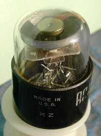 The most popular electron-ray tube was the 6E5 and its cousins, such as the 2E5 (lower heater voltage, but otherwise the same), the 6AB5/6N5, the 6U5/6G5, 2G5, 6H5 and 6T5. All used a 6-pin base and had the same connections, but could differ slightly in target voltages and sensitivity. A triode was included for the purpose of changing a small AVC voltage (say, up to -20 V) to the larger positive voltage needed for the control electrode. The Army-Navy version, the 1629, had a 12.6 V heater and octal base, in line with military standards, and this is the least expensive electron-ray tube at present, the others, where available, being more costly. The 6AF6/6AD6, a photograph of which is shown at the right, had two ray-control electrodes on opposite sides and no triode, while the 6AF7 had (it seems) twin sectors that moved concurrently. Finally, the 6AL7 had two rectangular displays that could be changed in size by control electrodes. These tubes are discussed below.
 A circuit for testing an electron-ray tube with a triode in the same envelope is shown at the left. The 1629 is recommended, as the cheapest and most widely available electron-ray tube. It operates exactly like the 6E5 and similar tubes, which are expensive and should be left to radio restorers. It is an attractive tube, and the internal construction can be seen clearly. Notice especially the continuation of the triode plate as the ray-control electrode. 200 V is required for proper operation, though voltages down to about 100 will give some result. My tube had a bright sector of only about 60°, though the rest of the target was faintly illuminated. The shadows of the support wires for the light shield were evident, showing the straight-line path of the electrons. When the north pole of a magnet was brought close, the electrons were deflected clockwise as seen from above, showing that they are negatively charged. The bright sector disappeared with zero bias, and closed for a grid voltage of -5.6 V. For even lower voltages, the bright sections overlapped, so the detection of this bias is rather sensitive. In this case, the ray-control electrode was obviously effective in accelerating electrons. A triode plate current of about 200 μA is required to bring the plate near ground, while -5.6 V cuts off the triode and the plate rises to the positive supply voltage.
 A circuit for testing a 6AF6 is shown at the right. The 6AF6 has two independent control electrodes which make two independent dark sectors. They are shown connected together in the diagram, but can be exercised separately as well. When grounded, they should give a wide sector of at least 90°, which should narrow as their voltage is brought up. The voltage is controlled manually here, but in practice a triode with a 510k plate resistor is used instead, operated by the AVC voltage on the grid. The lower the AVC voltage, the better the tuning, and the smaller the dark sector. You can easily try this yourself if you want. Some electron-ray tubes (e.g., the 6E5) actually include a triode just for this purpose. The 100k resistor is to protect the control electrodes in case you decide to rotate the pot all the way. With a target voltage of 161 V, 40 V on the control electrode shrunk the dark sector to 45°, and 97 V was enough to close it. One may suppose that a voltage 60% of the target voltage will generally do this.
 A curious kind of electron-ray tube is the 6AL7-GT. This tube was (they say) used as a tuning indicator in FM receivers, in which tuning was quite critical for good reception with early receivers. I never saw one, and do not know how they were used in practice, but the tube makes a fascinating example for study. The display is as shown at the left, which consists of two bars of greenish fluorescence, seen end-on to the tube. The internal structure is visible through the envelope, and a cross-section is also sketched. The cathode of the tube is horizontal (when the tube is vertical) instead of vertical, and only the electrons emitted upwards are used. There are beam-forming electrodes DJ1-DJ3 on either side of the cathode, below the grid. DJ3 extends over the whole width of both display bars, while DJ1 and DJ2 separately control the two bars on the other side. These electrodes are like the beam-forming electrodes in a beam-power tube, and have a similar action, which can be seen clearly here from the fluorescence. The grid seems to be a normal space-charge control grid, and was probably used to control the intensity of the fluorescence, as in a cathode-ray tube. The target anode TA accelerates and collects the electrons.
The TA voltage is relatively high, from 220 to 350 V, but the beam current is low. A beam current of 0.1 mA is just clearly visible, and 1 mA gives bright fluorescence. It is probably best not to exceed 1 mA. The voltages on the control electrodes are apparently meant to be negative (positive would probably short-circuit the beam), and their effects on the fluorescent bars can be studied if the negative biases are varied. DJ3 apparently controls one side of both bars, while DJ1 and DJ2 separately control the other ends of the bars. However, there seems to be considerable interaction between the controls. A sufficiently negative bias can extinguish the beam. What we have is essentially two voltage-controlled bars, which can be made quite narrow.
 The tube is also a triode, with the TA as plate. I ran characteristics for grid voltages from -1 to -6 V, and found μ = 43, rp = 370k, and gm = 120 μS. The low transconductance is to be expected, since only a portion of the emission is used, and the beam current is low. A voltage amplifier can be designed using the 6AL7, probably a service for which it never was intended. The example shown at the right gave a gain of -13 (it was supposed to be more like -19, but the parameters vary somewhat). The control electrodes were simply connected to the cathode, which gave wide bars, glowing softly with the beam current of 0.18 mA. The high plate voltage makes this an inconvenient amplifier, but it shows how any grid control can be used for amplification. This diagram also gives the pin connections for the tube.
VR Tubes
 Use a VR tube as a Zener to regulate voltage. I used a 0A3 or VR75 in the diagram at the left, which needs a supply of at least 105 V (so it will strike when turned on), and is in the normal glow region from 5 to 40 mA current. I used a "raw" 161 V supply, and a 10k resistor because I had a 1W one handy. This resistor should be sized to pass the full current required, up to 40 mA in a practical case. There is a jumper between pins 3 and 7 to put in the heater leads to the rectifier tube so that the supply cannot be started up with the VR tube removed. VR tubes are not quite as good as Zeners for voltage constancy. Once they decide on a voltage, it will be constant, but exactly what voltage that will be is uncertain. Like Zeners, VR tubes were used as a voltage reference in regulated power supplies. The OA3 has an orange-yellow glow (Ne); at this current level, it is easy to see that the glow does not cover the complete cathode, which is the tubular metal part. The anode is merely a central wire. My 0A3 gave 72.8 V when first turned on, and a steady 72.5 V after burn-in of about 30 minutes. These tubes make a very convenient regulated supply for experiments. Besides the 0A3, there are the 0B3 (90 V, violet glow, Ar?), 0C3 (105 V, blue glow, Xe), and 0D3 (150 V, pink glow, Kr), all with the same basing. The OD3 struck on the laboratory power supply described above, but not much current could be supplied with the resistor used.
Zener diodes are available up to 200 V at 5 W, so VR tubes are not necessary these days. The zeners do not give a nice glow, however.
The Thyratron
A thyratron is a gas-filled (argon at about 0.5 mmHg) triode, with a thermionic cathode ("thyra" is Greek for "door"). When the grid is held negative, it prevents conduction until the anode to cathode voltage is greater than some critical value that is linearly dependent on the grid voltage. The device acts similarly to a silicon controlled rectifier, except that it is voltage-controlled. Once conduction occurs, the grid loses all control, and the anode circuit must be opened to stop conduction. The 884 is a small thyratron for general use. The peak anode voltage is 300 V, and the peak anode current is 300 mA, but the operating current is 2 mA or less. A resistance greater than 25k must be in series with the grid to prevent excess grid current from flowing. The heater takes 6.3 V at 0.6 A (about twice the usual heater current).
 A relaxation oscillator circuit using an 884 thyratron is shown at the right. When the anode voltage was 101 V, and the grid voltage was -8.9 V, the circuit oscillated at 588 kHz, the capacitor voltage varying from 20 V to 86 V. Look at the capacitor voltage as a function of time while you vary the anode and grid voltages. There is an exponential charge to the firing voltage, then a very rapid discharge through the 1k resistor and the tube to extinction at 20 V. This signal could be used for a simple oscilloscope sweep circuit, and synchronized by a small positive pulse at the grid. The thyratron could also be used for phase control on an AC line, but the 884 cannot supply enough current for the usual applications. Larger mercury-vapor thyratrons were manufactured for this service that could handle several amperes.
The grid of a triode thyratron collects all the stray ions, which means that it cannot be used in a high-impedance control circuit. A second grid, the screen grid, is added to the thyratron to make a four-electrode or tetrode thyratron. In this case, the screen grid screens the control grid from the cathode, greatly increasing its impedance and allowing sensitive control. The second grid may be connected to the cathode, or may be varied in voltage around zero to control the striking voltage on the control grid.
 A good screen-grid thyratron is the 2D21, which is available at a very reasonable price. Its basing is shown at the right. The miniature envelope is the probable reason that its price is reasonable, since collectors prefer the ST envelope as "older-looking." The forward drop is quoted at 8 V, the peak forward voltage 650 V and the peak reverse voltage 1300 V. The maximum cathode current is 100 mA average, 500 mA peak. so it is rather more capable than the 884, whose average cathode current is only 75 mA.
 A practical sawtooth oscillator using the 2D21 is shown at the left. The screen grid is connected to the cathode. Control-grid bias is produced by the voltage divider of 100k and 820Ω. The charging current also flows through the 820Ω resistor, so the actual bias is about 2.5V rather that the 2.0V that the divider alone would supply. The 0.1 μF capacitor is to hold the cathode potential constant. A larger value would not be wrong. The 330k resistor and the 0.01 μF capacitor are the timing element. The resistor must be large enough that the current through it is less than the maintaining current of the discharge. Otherwise, the thyratron will simply fire and conduct, and fail to oscillate. The grid bias is sufficient to cause breakdown at about 160V. Replacing the 820Ω resistor by a smaller one would cause breakdown at lower voltages and give a more linear sawtooth of less amplitude.
This circuit oscillates with a free period of about 3.1 ms, or a frequency of 323 Hz. A signal generator can be used to inject a synchronizing signal to the grid, whose amplitude can be controlled by the 10k potentiometer. Try a sinusoidal signal of about 350 Hz. Slowly increase its amplitude and note the result. An amplitude of less than a volt will be found sufficient. If you change the frequency a little, the oscillator will follow up to a point. Note that you can lock the oscillator at twice its natural frequency, about 700 Hz, as well. If you look at the waveform at the control-grid input, you will notice a rather sharp positive pulse when the tube fires. This is probably the collection of positive ions, causing a voltage drop across the portion of the 10k pot between the grid and ground.
Of course, look at the output on the oscilloscope. The firing period is quite brief. During this time, the timing capacitor is connected directly across the tube and rapidly discharges. When conducting, the anode to cathode voltage is less than 10V. If you compare the 2D21 with the 884, you will note that a much smaller grid voltage is required for control, and that the control characteristic (firing voltage as a function of grid potential) is much steeper. To measure this characteristic, use a similar oscillator circuit where you can control the grid voltage. It is very difficult to measure the breakdown voltage in a static setup, while the oscilloscope will give the breakdown voltage directly.
An alternative to the 2D21 is the type 5727, which is similar to the 2D21-W. The -W simply indicates a ruggedized version, or one specified for military service.
Other Tubes
The tubes used here as examples are only an arbitrary selection, to show typical practice, especially the metal octal tubes that were so characteristic of the great days of radio. Later, the all-glass miniature tube was the preferred form, with 7 or 9 pins. You can use only 7-pin miniature tubes for your experiments, if you wish (although there are no miniature electron-ray tubes). The 0G3 is a glow-tube regulator (84 V), the 6C4 a medium-mu triode, the 6AV6 a high-mu triode, the 6BA6 a remote-cutoff pentode, and the 6AU6 a sharp-cutoff pentode, which can be substituted for the octal 0A3, 6J5, 6SF5, 6SK7 and 6SJ7, and all of which use a 7-pin base. The wonderful 6AN4 has been mentioned above. Dual triodes with 9-pin bases were very popular, such as the 12AU7, which was a dual 6C4, and the 12AX7, a dual 6AV6. Subminiature tubes were developed for computer use, normally dual triodes, and were used until the 1960's, along with miniature tubes. The early digital computers, such as the IBM 850, used vacuum tubes. There was even a "Mechano-Electronic Transducer," the type 5734 triode, whose plate was connected to an external shaft that could be rotated. Its sensitivity was 40 V/degree, and it was used to study vibrations.
The last great commercial application of vacuum tubes was in TV receivers, where semiconductors had difficulty with the high voltages and inductive kicks, so that vacuum tubes were still common in the 1970's, but even here they were gradually replaced by solid-state devices.
Older tubes had 4- or 5-pin bases, and often had grid caps on the top (to reduce capacitance). One series of tubes, whose designations began with "5" had heaters all taking 0.6 A, so they could be connected in series instead of in the usual parallel connection. Sometimes the heater voltages of the set of tubes for inexpensive AC-DC broadcast receivers added up to 117 V, while all taking the same current, of course, so they could be connected in series. Rectifier tubes often took 5 V at 2 or 3 A for their filaments, and this was standard enough that the typical power transformer always had a center-tapped 5 V winding. There were subminiature types for applications such as hearing aids, and designed for battery supply. Reference to any tube manual will show the full extent of this diversity of tube types.
Among other vacuum tube devices that may be used for experiments, small reflex klystrons (such as the 2K26), microwave oscillators, are available, but their prices are high. There used to be war-surplus small klystrons, used, I believe, as local oscillators in radar sets, that were very useful for microwave demonstrations. Magnetrons are also available, since they are used in microwave ovens. However, make sure your will is in good shape before you investigate the insides of either a microwave oven or a TV receiver. Both contain extremely dangerous voltages and lethal surprises, and they cannot teach much anyway, so they are best avoided. The photomultiplier is still in use, because of its exquisite sensitivity, made possible by secondary electron emission from its dynodes (as they are called). See Phototubes for more details. Photomultipliers are slightly beyond our scope, however, as is the magnetron. Both demand fairly high voltages and are expensive.
References
Vacuum tubes were very intensively studied, both theoretically and practically, and were at the center of electronics during their era. Any textbook on electronics prior to 1960 will treat vacuum tubes extensively. Texts were also written explicitly on the physics of vacuum tubes. Amateur radio operators often built their own equipment in those days, especially transmitters, so many construction articles give insight into the use of vacuum tubes in communications.
Vacuum tubes, sockets and high-voltage transformers can be obtained from Tubes And More, the website of Antique Electronic Supply, 6221 S. Maple Ave, Tempe, AZ 85283. A free catalog can be ordered from the website, and on-line purchasing works very well. Another source is Vacuum Tubes, Inc.. Many tubes are available for less than $5.00 each, a good value, taking care to avoid the ones in demand for antique radios, musical instruments and hi-fi amplifiers.
A good tube manual is the RCA Receiving Tube Manual (Harrison, NJ: Radio Corporation of America, 1959). It is out of print, but available in reprint from Antique Electronic Supply for $12.95 (Original price $0.75). Older editions of the ARRL Amateur Radio Handbook contained extensive information on vacuum tubes. I use the 1954 edition. The definitive tube manual was the loose-leaf edition from RCA, in several volumes. I have not seen one recently, but the data may be available on CD.
Vacuum-tube basing and data, with some characteristic curves, is available over the internet from C&J Radio. This site may have vanished. A good alternative is Duncanamps, which has a tube data facility.
An excellent text on free electron devices, including the physics of thermionic emission, derivation of the Langmuir-Child expression, movement of charged particles in electric and magnetic fields, and discharges in gases, is J. Millman and S. Seely, Electronics (New York: McGraw-Hill, 1951). There has been no subsequent text at this advanced undergraduate level covering the same material with the same skill, to my knowledge.
F. Langford-Smith, The Radiotron Designer's Handbook (Sydney, Australia: Amalgamated Wireless Valve Company Pty. Ltd., 1953, reproduced and distributed by RCA, Harrison, NJ) is a famous and comprehensive handbook of radio receiver and audio lore. It is also available from Antique Electronics Supply in reproduction at a considerable advance on its original cost of $7.25.
G. F. J. Tyne, Saga of the Vacuum Tube (Tempe, AZ: Antique Electronic Supply, 1994) is an excellent history of early thermionic vacuum tube development, from Fleming and de Forest up to 1930, with many illustrations.
The Impoverished Radio Experimenter, Vol 1 (Bradley, IL: Lindsay Publications, 2000) is an excellent introduction to experimenting with vacuum tubes, with information on early tubes and their development. The author is a very knowledgeable and skilled experimenter. Hints for building a low-cost power supply, and a simple radio receiver, are included. Not satisfied with just winding coils, he also home-brews a variable capacitor! Also available from Antique.
Return to Electronics Index
Composed by J. B. Calvert
Created 17 August 2001
Last revised 8 April 2003