Modulators and Hybrids
Introduction
In this unit, we shall treat two kinds of circuits that are very useful in communications, but are often poorly explained in textbooks. They are the ring modulator, which uses four diodes and two transformers to make a very good balanced modulator, and the hybrid transformer, used for separating propagation directions in converting a duplex circuit to a four-wire circuit, and vice versa. Both of these circuits can be inexpensively constructed and tested, and doing so should clarify your understanding of them. Electronics texts typically treat neither, though important principles are involved.
Modulators
We have already met amplitude modulation and balanced modulators in Unit 19, but we shall look further into the matter here, and describe some circuits suggested by telephone carrier systems, and try to make it clear how these somewhat mysterious circuits function. A telephone carrier system shifted the frequency of a voice channel to a higher band, say from 300-3000 Hz to 5300-8000 Hz. This signal could be transmitted over a circuit in addition to an ordinary voice channel, and the two channels separated by filters so that the shifted channel could be restored to its normal band at the destination, a process called detection or demodulation. This was originally done with open-wire circuits, since they had low attenuation, and later with coaxial cables, when up to 12 full-duplex channels could be sent over one coaxial cable. This was later extended to microwave relay links, and has become normal practice.
The circuits that made this possible were those that shifted frequencies, those that separated different frequency bands, and those that could separate a full-duplex channel into transmitting and receiving channels, as well as their inverses, which happen to be performed by the same circuits. Let's first look at the shifting circuits, the modulators, and then at the separating circuits, the hybrids.
An amplitude modulated wave with modulation fraction m can be expressed as f(t) = (1 + m sin ωt)sin ω't. Here, the signal component has angular frequency ω, and ω' is the angular frequency of the carrier component. The resulting signal is a sine wave whose amplitude varies so that the profile of the curve is exactly the signal waveform. It can be converted back to the signal waveform by rectification and filtering, a simple process that explains the popularity of this kind of modulation. Note that the amplitude of the carrier wave does not change sign when -1 ≤ m ≤ 1. If it does, we have overmodulation. The percent modulation is 100|m|. If the amplitude does not reach zero, we have less than 100% modulation, or undermodulation. If the amplitude is constant, we have 0% modulation, or just the unmodulated carrier.
Using the trigonometric formula for expressing the product of two sines as a sum of sinsoids, we find that f(t) = sin ω't + (m/2)cos[(ω' - ω)t] - (m/2)cos[(ω' + ω)t]. The function is expressed as the sum of the carrier, and two sidebands, one the difference of the carrier and signal frequencies, and one the sum, called the lower and upper sidebands. By choosing the carrier frequency sufficiently high, the signal band ω1 to ω2 can be shifted to the band ω' + ω1 to ω' + ω2, of the same width but of higher frequency. We assume that the carrier frequency is high enough that the baseband and the shifted bands do not overlap.
The unmodulated carrier carries no information; it merely provides a frequency reference for the sidebands. If we assume that the carrier frequency is known and can be reproduced, then it is only necessary to transmit one of the sidebands. This sideband is produced with the aid of the carrier at the transmitting station, and is demodulated at the receiving station with the aid of a copy of the carrier. This procedure is called SSB-SC, or single sideband, suppressed carrier, and is widely used in radio. Analog television is also transmitted SSB, but with a small amount of carrier retained for synchronization purposes. 2/3 of the power in a 100% modulated wave is in the carrier, only 1/3 in the sidebands. Only 1/6 of the total power is actually necessary to transmit the information. SSB-SC not only saves bandwidth, but power.
The circuit used to produce the modulated carrier must have as inputs the carrier and signal frequencies. Since new frequencies are introduced, no linear circuit can possibly do the job. There are many possible circuits; we shall consider only a balanced modulator that produces both sidebands, but the carrier does not appear in the output. This signal must be simply the product g(t) = sin ωt sin ω't. This looks rather different from the AM signal f(t) that we have been considering. The amplitude of the carrier now varies from +1 to -1. Imagine the signal wave and a copy multiplied by -1, and superimposed so that the nodes coincide. Now imagine this as the envelope of a wave of about the carrier frequency. This is what the superposition of the two sidebands looks like.
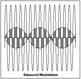 The diagram at the right shows the high-frequency carrier wave superimposed on the signal wave. The carrier cuts the signal wave into slices. If we multiply each slice by ±1 depending on whether the carrier is positive or negative during that slice, then we get a wave looking very much like the modulated wave we desire, as the shaded areas show. This suggests that we can make a modulator by letting the carrier control switches that connect the signal with either sign to the output.
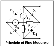 The simplest way to do this is with the ring modulator, which uses diodes as switches. The principle of the ring modulator is shown at the left. When ec makes the top node sufficiently positive, D2 and D4 will be forward-biased, while D1 and D3 will be open, and the signal generator es will be connected to the output with one polarity. When ec makes the bottom node positive instead, D1 and D3 will conduct, connecting es to the output with the opposite polarity. This is the desired action, but there will be carrier at the output as well, so this circuit is not a balanced modulator. We see in this circuit, though, how the carrier voltage can control diodes to open and close connections. I have not investigated this circuit experimentally.
The ring modulator is not the only way to create sidebands, but it is a very easy and effective way. An analog multiplier can also be used, as described in Unit 30. Traditionally, an AM wave was created by changing the gain of an RF amplifier in time with the modulating signal, or by the use of a nonlinear amplifier. It is very inconvenient to build a ring modulator from vacuum diodes, but the circuit was made practical with the invention of solid-state rectifiers, the first of which was the copper-oxide rectifier. These were first used in the high-frequency, multichannel Type J and Type K telephone carrier systems of the late 1930's. Germanium or silicon diodes are, of course, much superior in this application, and are now used exclusively.
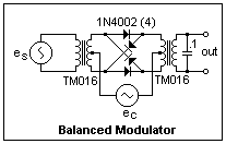 We may use audio transformers to make a balanced modulator. In the circuit at the right, two Mouser TM-016 1:1 600ΩCT transformers are used. These are inexpensive, and excellent things to have a couple of handfuls of on hand. The signal passes through both transformers to the output, while the carrier is introduced at the centre taps. It is easy to see that there will be no output at the carrier frequency because of cancellation in the transformer windings. Nevertheless, the controlling voltage will be applied to the diodes. The top and bottom diodes will conduct when the carrier is positive on the left, while the inclined diodes will conduct with the opposite polarity. Note that the signal current does not pass through both diodes in the forward direction in either case, as it did in the preceding circuit, and that the diodes are not connected as in a full-wave bridge rectifier. A closed path can be traced through the four diodes in the forward direction, which explains the name of "ring modulator." The switching action of the diodes is to reverse connections to the second transformer. The 0.1 μF capacitor is to catch the inductive spikes that occur on switching. By all means remove this capacitor when you test the circuit and see what happens.
To test the circuit, connect your good signal generator to the carrier input, and set it for sine wave output with zero DC component, at about 5000 Hz. Connect another signal generator to the signal input, and set it the same way, but to about 500 Hz. If you do not have two sine-wave generators on hand, consult Unit 19 for building sine-wave generators from XR-2206 or similar IC's. Connect the output to an oscilloscope. Let the signal input be 2 V peak-to-peak and the carrier about 8 V peak-to-peak. Vary the input voltages to see what happens, after you have the circuit working. If the circuit is correct, you will see a very good double-sideband, suppressed-carrier signal. This is the superposition of sidebands at 5500 Hz and 4500 Hz (or whatever the actual frequencies may be).
Let's suppose that you have built a sharp-cutoff low-pass filter with cutoff at 5000 Hz, and filter the ouput of the modulator with it, obtaining a relatively pure 4500 Hz sideband signal. If you vary the signal frequency a little, the sideband frequency will vary as well. If you have also built a second modulator circuit, feed it with the sideband and the same 5000 Hz carrier. In the output, you should have 9500 Hz and 500 Hz signals, which are easy to separate by a filter (a copy of the one you used to get the sideband). Now you have 500 Hz in, 500 Hz out. If you vary the input amplitude or frequency, the output amplitude or frequency should vary accordingly. This is a complete half-duplex carrier-frequency link, and should work very well, if you take the trouble to put it together. The important thing we have illustrated here is the frequency-shifting that is behind it all. We still have to consider how to put multiple signals on the same line, and how to handle the directions of transmission.
Hybrids
A telegraph line was always ready for communication in either direction. When one operator was sending, the other was receiving, so that messages could be sent in either direction, but not at the same time. The capacity of the line could be doubled if one operator was sending, and another receiving, at each end of the line. However, the sending operator would also work the sounder at his end of the line, as well as the distant sounder, so the two messages would be confused. A circuit was needed that would cause the sounder to be operated only by signals from the other end of the line, not by signals from the local office. Then, both operators could send over the same wire independently, without interference. Such a circuit was called a duplex.
 There were two main kinds of telegraph duplex circuits. One kind used a relay with two windings, and another was the bridge duplex shown at the right. The bridge duplex was a precursor of the hybrid, so its study is worth while. R1 was equal to R3, and R4 was adjusted to be equal to R2. R2 was the equivalent resistance presented by the line and the set at the other end; it was mainly the line resistance, and did not change much whether the key at the other end was pressed or not. When the key was closed, the voltages at each end of the local relay coil would be the same, and the sounder would not sound. However, when the key at the other end of the line was closed, the line voltage went up, and operated the sounder.
It is not immediately obvious, but analyzing the circuit will show that the relay will operate whether or not the local key is open or closed, so that it is controlled by the distant key in any case. The original telegraph circuit is called half-duplex, permitting communication in either direction, but only one direction at a time. The duplex circuit is also typical of ordinary telephone operation, when simultaneous talking could be done at both ends, were there any need for it. A circuit in which there are separate channels for each direction is called a four-wire circuit (whether four wires are actually used or not). A simplex circuit is something quite different: the two wires of, say, a telephone circuit, are used as one wire, with a ground return. The telegraph circuit is said to be simplexed on the telephone circuit. It has nothing to do with directions of communication.
Notice especially resistance R4. It is really a dummy line made to resemble the actual line, in this case by adjusting the resistance. More complicated dummy lines were actually used in duplex circuits, that involved capacitance as well. We will see that dummy lines are a feature of all the circuits investigated here.
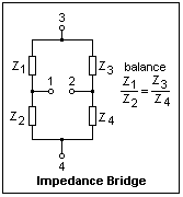 The figure at the left shows an impedance bridge, which is simply two voltage dividers. When the bridge is balanced (the condition for balance is shown in the figure), a voltage applied at terminals 3-4 causes zero voltage between terminals 1-2, and vice versa. This Wheatstone Brigde principle is the principle used not only in the duplex telegraph circuit just described, but in all the hybrid circuits as well, so it should be kept clearly in mind when analyzing them.
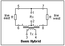 A basic hybrid circuit is shown at the right. If you look at it carefully, the bridge should be evident. Terminals 3-4 are the energy input to the bridge, here magnetically coupled. Terminals 1-2 have zero voltage between them when the bridge is balanced, which means that the resistances connected to 5-6 and 7-8 are equal. These resistances represent the resistances of the transmission line to the right and left. When terminals 3-4 are excited, equal amounts of energy are supplied to the lines. This circuit can be constructed using a Mouser TM-016 transformer with a centre-tapped secondary, and using only half of the primary, and with resistors of any convenient value, say 680Ω. When you connect a signal generator to 3-4, you will measure zero (almost) voltage across 1-2, and equal voltages across 5-6 and 7-8.
I do not know the origin of the term "hybrid." A hybrid is the offspring of differing parents, and it is not clear to me why this term is used for this bridge circuit. A possibility is that when it replaced the inductor (transformer) in a telephone set, it combined functions previously performed by different circuits.
Now put a resistance across 3-4, and move the signal generator to 5-6, removing the resistor there. It will be replaced by the internal resistance of the signal generator, so the circuit will still be approximately balanced. Now you will measure a voltage across 3-4 and, importantly, across 1-2 as well. If the input to an amplifier is connected to 1-2, and its output to 3-4, the gain of the amplifier can be increased to a significant amount without danger of oscillation. The circuit is, in effect, a feedback network for the amplifier, and the loop gain is so small that the circuit will not oscillate. This is the primary and essential action of a hybrid circuit.
We have, in fact, made a simple type 21 telephone repeater. This repeater can be placed in the middle of a long circuit, and will considerably extend its range. The energy from the amplifier is sent both ways along the lines, which can cause problems if we try to use more than one type 21 repeater (they will play "ping-pong"). Also, the lines on each side must be nearly identical for balance. Nevertheless, the circuit is a practical duplex repeater, and was at one time used to a certain extent.
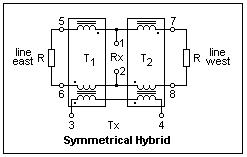 A more symmetrical circuit, and the one actually used, is shown at the left. The windings driving the lines are split into halves, with each half driving one side of the line. Usually, two transformers with three similar independent windings are used. The core in each transformer links all three coils, and the coils are phased as shown. The two transformers are together called a hybrid transformer. The Mouser TM-028 is designed for this use. In fact, the TM-028 would be better in the previous circuit, since the coils are symmetrical. This circuit can be constructed and tested like the last one, and should work equally well. Textbooks do not do a very good job of explaining this circuit, or of showing how to build one. None that I have seen make it clear that the windings in the two line wires are on the same core, or that the coils are phased as shown.
Note that the hybrid does not cleanly separate the signals in both directions. It generates signals going in both directions, one on each of the lines. In most cases, one of the lines is actually a dummy. An incoming signal does appear at 1-2, but it also appears at 3-4, where it does no damage since amplifiers are unilateral. A microwave directional coupler does a cleaner job, but the telephone hybrid is good enough.
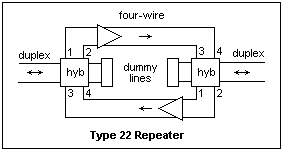 A better repeater is the type 22 repeater, which converts the duplex signal into a four-wire signal and then amplifies each direction separately. One hybrid is used at each end, each working into a dummy line. The dummy line can be matched to the line it is to represent, and multiple repeaters can be used. In modern practice, only the subscriber loop is duplex, and everything else is four-wire. With four-wire, of course, hybrids are not necessary, and amplifiers can be inserted wherever necessary. Transformer hybrids only work well at audio frequencies, so when higher frequencies were used, four-wire was the only solution.
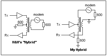 Horowitz and Hill, usually so reliable, have a hybrid circuit that I cannot get to work, and which seems basically flawed. The diagram shows their circuit on the left, and my redesign at the right, which does work. In their circuit, the voltage drop across the 600Ω resistor is opposite to that of the transformer winding, and they do compensate to some degree, but by no means well enough. If you transmitted into their circuit, a lot of signal would (does) come back in the Rx line. The change is only a rearrangement of the components, but where they go makes considerable difference.
The hybrid transformer can be used in a telephone set for reduction of sidetone. Sidetone is hearing your own voice in the receiver while speaking into the transmitter. A certain strength of sidetone is necessary for normal conversation. If it is too strong, one will tend to speak too softly, while if it is too weak, one will tend to shout. The receiver is connected to terminals 1-2, and the transmitter to terminals 3-4, while the line corresponds to one of the resistive legs. If the hybrid is perfectly balanced, there will be no sidetone at all. It can be unbalanced to give the desired degree of sidetone. The hybrid, or its equivalent, is part of the "speech network" module of the modern telephone set.
References
A. L. Albert, Electrical Communication, 2nd ed. (New York: John Wiley & Sons, 1940). pp. 420-423, 434-462. Good treatment of historical carrier systems, from Type A to Type K.
R. S. Glasgow, Principles of Radio Engineering (New York: McGraw-Hill, 1936). pp. 220-222. Modern circuits, electronics and communications texts do not even mention the hybrid transformer.
P. Horowitz and W. Hill, The Art of Electronics, 2nd ed. (Cambridge: Cambridge University Press, 1989). p. 728.
Return to Electronics Index
Composed by J. B. Calvert
Created 6 September 2003
Last revised
 The diagram at the right shows the high-frequency carrier wave superimposed on the signal wave. The carrier cuts the signal wave into slices. If we multiply each slice by ±1 depending on whether the carrier is positive or negative during that slice, then we get a wave looking very much like the modulated wave we desire, as the shaded areas show. This suggests that we can make a modulator by letting the carrier control switches that connect the signal with either sign to the output.
 The simplest way to do this is with the ring modulator, which uses diodes as switches. The principle of the ring modulator is shown at the left. When ec makes the top node sufficiently positive, D2 and D4 will be forward-biased, while D1 and D3 will be open, and the signal generator es will be connected to the output with one polarity. When ec makes the bottom node positive instead, D1 and D3 will conduct, connecting es to the output with the opposite polarity. This is the desired action, but there will be carrier at the output as well, so this circuit is not a balanced modulator. We see in this circuit, though, how the carrier voltage can control diodes to open and close connections. I have not investigated this circuit experimentally.
 We may use audio transformers to make a balanced modulator. In the circuit at the right, two Mouser TM-016 1:1 600ΩCT transformers are used. These are inexpensive, and excellent things to have a couple of handfuls of on hand. The signal passes through both transformers to the output, while the carrier is introduced at the centre taps. It is easy to see that there will be no output at the carrier frequency because of cancellation in the transformer windings. Nevertheless, the controlling voltage will be applied to the diodes. The top and bottom diodes will conduct when the carrier is positive on the left, while the inclined diodes will conduct with the opposite polarity. Note that the signal current does not pass through both diodes in the forward direction in either case, as it did in the preceding circuit, and that the diodes are not connected as in a full-wave bridge rectifier. A closed path can be traced through the four diodes in the forward direction, which explains the name of "ring modulator." The switching action of the diodes is to reverse connections to the second transformer. The 0.1 μF capacitor is to catch the inductive spikes that occur on switching. By all means remove this capacitor when you test the circuit and see what happens.
 There were two main kinds of telegraph duplex circuits. One kind used a relay with two windings, and another was the bridge duplex shown at the right. The bridge duplex was a precursor of the hybrid, so its study is worth while. R1 was equal to R3, and R4 was adjusted to be equal to R2. R2 was the equivalent resistance presented by the line and the set at the other end; it was mainly the line resistance, and did not change much whether the key at the other end was pressed or not. When the key was closed, the voltages at each end of the local relay coil would be the same, and the sounder would not sound. However, when the key at the other end of the line was closed, the line voltage went up, and operated the sounder.
 The figure at the left shows an impedance bridge, which is simply two voltage dividers. When the bridge is balanced (the condition for balance is shown in the figure), a voltage applied at terminals 3-4 causes zero voltage between terminals 1-2, and vice versa. This Wheatstone Brigde principle is the principle used not only in the duplex telegraph circuit just described, but in all the hybrid circuits as well, so it should be kept clearly in mind when analyzing them.
 A basic hybrid circuit is shown at the right. If you look at it carefully, the bridge should be evident. Terminals 3-4 are the energy input to the bridge, here magnetically coupled. Terminals 1-2 have zero voltage between them when the bridge is balanced, which means that the resistances connected to 5-6 and 7-8 are equal. These resistances represent the resistances of the transmission line to the right and left. When terminals 3-4 are excited, equal amounts of energy are supplied to the lines. This circuit can be constructed using a Mouser TM-016 transformer with a centre-tapped secondary, and using only half of the primary, and with resistors of any convenient value, say 680Ω. When you connect a signal generator to 3-4, you will measure zero (almost) voltage across 1-2, and equal voltages across 5-6 and 7-8.
 A more symmetrical circuit, and the one actually used, is shown at the left. The windings driving the lines are split into halves, with each half driving one side of the line. Usually, two transformers with three similar independent windings are used. The core in each transformer links all three coils, and the coils are phased as shown. The two transformers are together called a hybrid transformer. The Mouser TM-028 is designed for this use. In fact, the TM-028 would be better in the previous circuit, since the coils are symmetrical. This circuit can be constructed and tested like the last one, and should work equally well. Textbooks do not do a very good job of explaining this circuit, or of showing how to build one. None that I have seen make it clear that the windings in the two line wires are on the same core, or that the coils are phased as shown.
 A better repeater is the type 22 repeater, which converts the duplex signal into a four-wire signal and then amplifies each direction separately. One hybrid is used at each end, each working into a dummy line. The dummy line can be matched to the line it is to represent, and multiple repeaters can be used. In modern practice, only the subscriber loop is duplex, and everything else is four-wire. With four-wire, of course, hybrids are not necessary, and amplifiers can be inserted wherever necessary. Transformer hybrids only work well at audio frequencies, so when higher frequencies were used, four-wire was the only solution.
 Horowitz and Hill, usually so reliable, have a hybrid circuit that I cannot get to work, and which seems basically flawed. The diagram shows their circuit on the left, and my redesign at the right, which does work. In their circuit, the voltage drop across the 600Ω resistor is opposite to that of the transformer winding, and they do compensate to some degree, but by no means well enough. If you transmitted into their circuit, a lot of signal would (does) come back in the Rx line. The change is only a rearrangement of the components, but where they go makes considerable difference.