| |
Abstract and Notes
|
|
Ground-Penetrating
Radar (GPR) Mapping as a method for planning excavation strategies,
Petra, Jordan
 Correlation of Excavated Features and
Stratigraphy to GPR Maps and Profiles
Correlation of Excavated Features and
Stratigraphy to GPR Maps and Profiles
- The GPR maps and profiles showed a number of interesting buried
features, which were targeted for excavation. An assessment
of the accuracy of the GPR data was then made by correlating profiles
and maps to the excavated features.
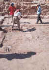
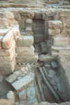
- During GPR data collection in Grid 1, a very distinctive feature
was visible on the radar system computer screen that appeared to
be a platform with a distinct edge or wall, bounded on the west
by an area with little radar reflection. It appeared that
this was an architectural feature on the edge of an open area, perhaps
the garden. Excavation of the feature began immediately, even
before the data were processed. Figure 33 below shows the
uncovering of the west wall of this feature in exactly the location
predicted by GPR.
Figure
33
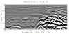
- The processed data of one of the profiles that was collected directly
over this feature showed a distinct paved surface, with one step
down to west and a larger drop into an area where there was no significant
architecture (Figure 2). The interior of the platform showed
a number of reflections, as would be produced from many rocks in
a rubble fill.
Figure
2
- Figure 34 illustrates the interpretation of the profile in Figure
2, which crossed the feature from east to west.
Figure
34
- Trench 5 was then placed to fully uncover this feature (Figure
35). The platform and step seen in the GPR data were revealed.
Figure
35
- This platform appeared to be somehow related to the water distribution
systems, discovered in earlier excavations to the south (Figure
9). It had a small water basin on its southern wall, which
may have been connected to the water distribution system found in
earlier excavations just to the south.
Figure
9
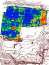
- The platforms are visible in the amplitude slice-maps in the southwestern
corner of the grid, in this slice from 25-50 cm (Figure 18).
They are visible in the map as red features, indicating high amplitude
reflections.
Figure
18
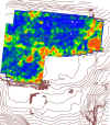
- In the slice from 50-75 cm (Figure 19) the platforms can be seen
as red anomalies in the bottom right side of the grid. The
blue color to the west indicates open areas with no architecture,
which could be the garden areas adjacent to the platforms.
Figure
19
A Second Platform Revealed
- A second feature that appeared to be another platform was also
visible in Grid 1 to the north. It appeared in reflection
profiles (Figure 36) to be a series of walls, or perhaps a partially
collapsed platform, similar to the one excavated just to the south.
This feature is also bounded on the west by the same open area.
Figure
36
- Figure 37 is our interpretation of this profile (after the main
feature was excavated). We found that what appeared to be
three walls on the right end of the profile were actually a platform,
similar to the one just to the south.
Figure
37
- This architectural feature was excavated in Trench 2 (Figure 38).
A platform was found, much like that in Trench 5, but a portion
of its top had been robbed of stone, making it appear in GPR profiles
to look like a series of walls.
Figure
38
- A detailed profile crossing this feature (Figure 39) clearly shows
the east and west walls of the platform, with the hole in the middle
where stones were removed, perhaps to be used in construction elsewhere
at the site.
Figure
39
Discovery of the North Building
- In Grid 2 (Figure 24), where our detailed radar profiles were
collected, there were two targets for excavation: the large buried
building, which we called the North Building, and the distinct strata
outside the building. The strata were postulated to be the
remains of gardens in the open areas between the buildings.
Figure
24
- Trench 6 was placed to encounter the southeast corner of the building
and Trench 8 for the northwest corner (Figure 40).
Figure
40
- Profile 54 (File 54 ) crosses the east wall of the structure at
an oblique angle (Figure 40). The north and east walls are
visible, as well as two distinct strata outside the structure, which
we hypothesized might be the remains of garden soils (Figure 25).
A deeper reflection north of the structure showed up on the renderings
as a linear feature (Figure 24), which we hypothesized might be
an ancient water pipe.
Figure
25
- Trench 6 was placed to encounter Corner A (Figure 27).
Figure
27
- Corner A of the North Building was uncovered in the exact location
mapped by GPR. We were somewhat surprised, however, to find
that this corner had an extending wall to the south. A closer
look at the slice-map (Figure 27), however, showed this extension,
but as it was right at the edge of Grid 2 it was not at first recognizable.
To the east of Corner A (an area which had not yet been uncovered
when the photo in Figure 41 was taken) two organic-rich buried soil
horizons were discovered, which were predicted in the two-dimensional
profiles (see Figure 25).
Figure
41
Discovery of an Agricultural Soil
- The northwest corner of the North Building was chosen for excavation
in Trench 8, where corner B was mapped (Figure 27).
Figure
27
- Corner B of the structure was encountered in the correct location
according to the GPR maps (Figure 42). The trench was also
deepened outside the structure to test other distinct strata visible
in the GPR profiles. These also turned out to be buried garden
soils horizons.
Figure
42
- Although we did not recognize the hole in the southern platform
(Figure 38) as such immediately, it made perfect sense after we
uncovered the feature. Our initial interpretation was that
there were three walls next to each other (which didn't make much
sense), because there were three distinct reflection hyperbolas
(Figure 39). We now understand that the hyperbolas were created
by the highly reflective corners and top of the platform.
Figure
39
- A closer look at the profiles adjacent to File 43 (Figure 39),
would have shown this platform to be intact to the north and south.
It was the hole in the platform (Figure 38) that fooled us into
believing there were a series of walls in this area.
Figure
38
- We also did not recognize the wall extension to the south of Corner
A in the North Building, because it was at the edge of the grid
(Figure 27). In the future we will make our grids much larger
than may seem absolutely necessary so that all features associated
with the buried architecture will be visible.
Figure
27
- Almost all the other architectural and stratigraphic features
visible in the GPR profiles and mapped were found in the locations
predicted. Many features, such as the possible deep pipe (thought
to be a Roman water line) to the north of the North Building, await
excavation.
|
|


