| |
Abstract and Notes
|
|
Ground-Penetrating
Radar (GPR) Mapping as a method for planning excavation strategies,
Petra, Jordan
GPR Theory of Operation
 The
GPR Method The
GPR Method
- Radar pulses are generated at a surface antenna and then propagated
into the ground. When they encounter buried discontinuities (for
instance stones surrounded by sand or changes in the composition of
stratigraphic units), a portion of the radar energy is reflected back
to the surface and recorded again at the antenna.
- When the velocities of the radar travel-times are calculated they
can be converted to depth, making GPR a three-dimensional geophysical
tool.
Recording
Radar Reflections
- Antennas are moved along the ground surface in transects within a
grid.
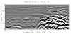
- Many reflections are recorded per second and when they are plotted
in a vertical profile a two-dimensional vertical "slice" of
reflections in the ground is produced.
Figure
2
- When many transects are collected in a grid a three-dimensional data
base is obtained.
Figure
3

Depth
of Penetration and Resolution
- The depth of penetration, and the resolution of buried features is
primarily controlled by the frequency of the antenna.
- At the "Lower Market" a 400 megahertz (MHz) frequency antenna
was used, which allows a maximum depth of penetration of about 3 meters
and can resolve features as small as about 10 cm in diameter.
Figure
11

How
Materials in the Ground Affect the GPR Signal
- As radar energy moves through the ground, any discontinuity will reflect
energy back to the surface.
- Radar energy spreads out in a conical pattern as it moves into the
ground.
Figure
12

- As energy penetrates past a certain threshold it is absorbed by the
earth and spreads out until it is finally lost.
Computer
Processing to Produce Images of Features in the Ground
- Standard GPR processing produces two-dimensional vertical profiles
of each reflection transect.
- The high amplitude reflections, generated from buried materials with
a high physical or chemical contrast, show up as distinct black and
white reflections on the profiles. Areas of homogeneous
material with little contrast show up as shades of gray.
Figure
2
- A series of three-dimensional maps can be produced using what are
called amplitude time-slices.
- This processing method produces contoured maps of the relative amplitudes
of reflections in specific horizontal slices in the ground.
Figure
13

- Using this mapping method each time-slice becomes analogous to a map
of all materials in arbitrary excavation levels.
- Data from time-slice maps can also be imported into rendering programs
to produce three-dimensional images of reflections in the ground that
mimic the buried features
|
|


